Oil and air separation structure for hydraulic retarder

A technology of hydraulic retarder and separation structure, applied in the direction of hydraulic resistance brake, brake type, mechanical equipment, etc., can solve problems such as oil waste and environmental pollution, and achieve the effect of avoiding waste and reducing pollution

Active Publication Date: 2013-10-02
NINGBO HUASHENG AUTOMOBILE PARTS
View PDF6 Cites 8 Cited by
  • Summary
  • Abstract
  • Description
  • Claims
  • Application Information

AI Technical Summary

Problems solved by technology

[0004] But when the compressed air is discharged through the exhaust channel in the hydraulic retarder of the above prior art, a certain amount of oil is often contained in the compressed air, and the oil contained in the discharged compressed air will pollute the surrounding environment, and Also wastes oil

Method used


Image

  • Oil and air separation structure for hydraulic retarder
  • Oil and air separation structure for hydraulic retarder
  • Oil and air separation structure for hydraulic retarder

Examples


Embodiment Construction

[0021] The present invention will be described in further detail below with reference to the accompanying drawings and specific embodiments.

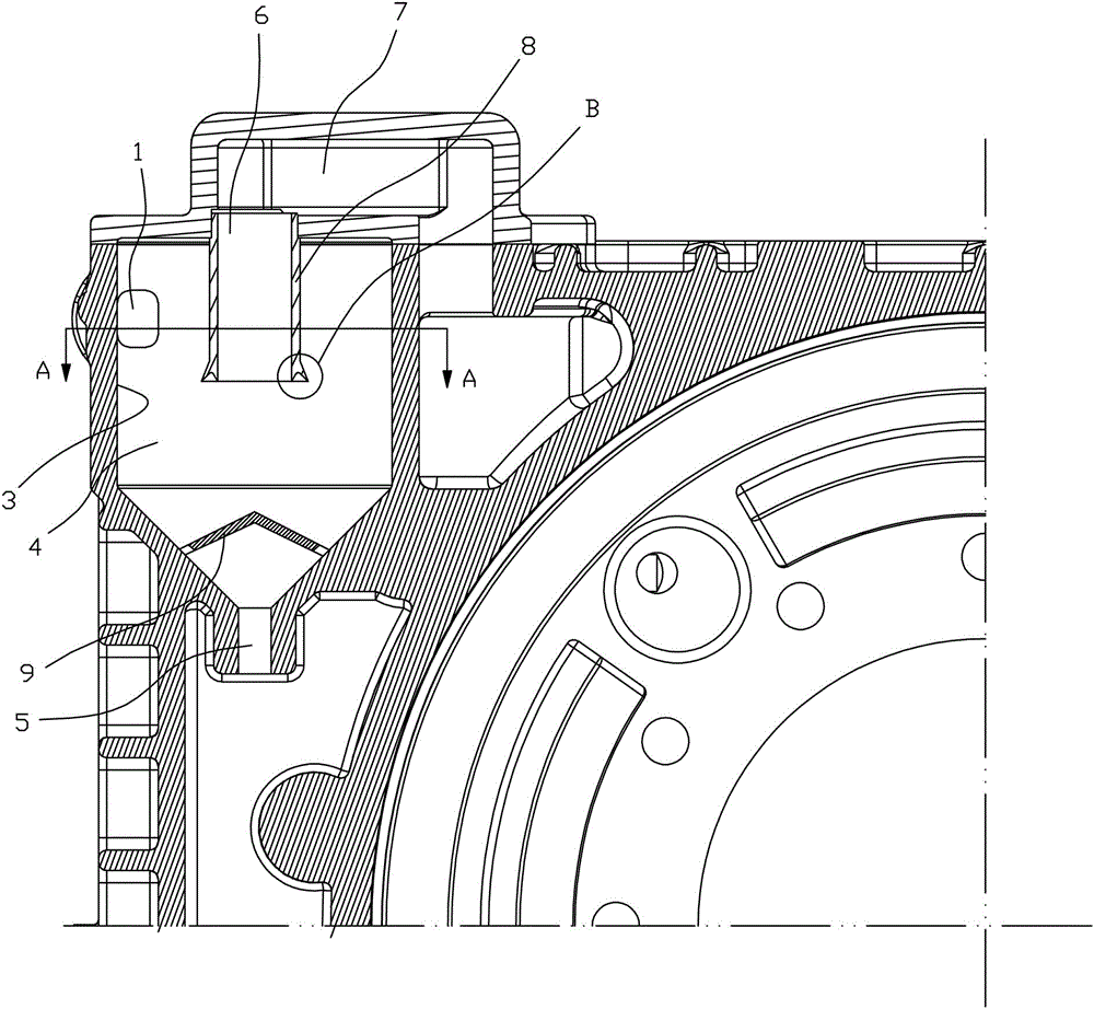
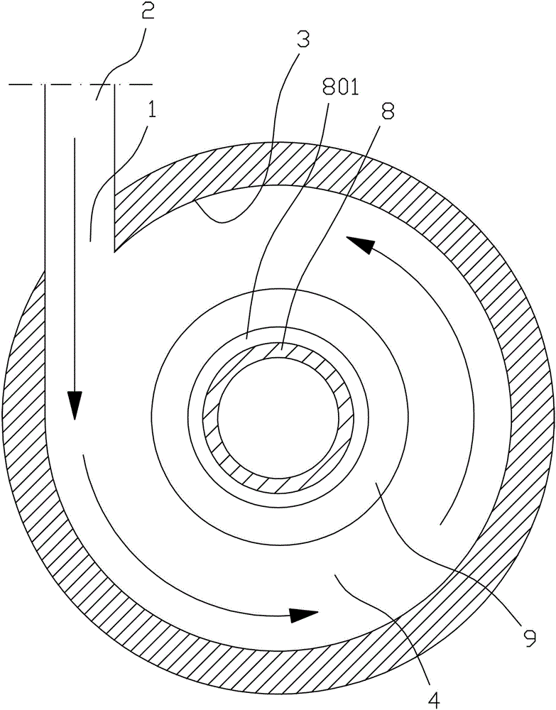
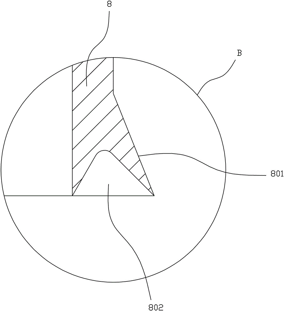
[0022] Depend on figure 1 , figure 2 , image 3 As shown, the oil-gas separation structure of a hydraulic retarder of the present invention includes an exhaust channel and an oil return channel on the hydraulic retarder, one end of the exhaust channel communicates with the oil storage chamber, and the other end of the exhaust channel communicates with the oil storage chamber. The external atmosphere is connected, one end of the oil return passage is provided with an oil collection hole for collecting the oil leaked from the working chamber, the other end of the oil return passage is connected with the oil storage chamber, and the exhaust passage is connected in series with a Compressed air separates oil and gas and returns the separated oil to the oil storage chamber through the oil return channel, that is to say, the exhaust channel...


PUM


Abstract

The invention discloses an oil and air separation structure for a hydraulic retarder. The oil and air separation structure comprises an exhaust passage and an oil return passage, wherein one end of the exhaust passage is communicated with an oil storage cavity, the other end of the exhaust passage is communicated with the external atmosphere, one end of the oil return passage is provided with an oil collecting hole used for collecting oil leaked from a work cavity, the other end of the oil return passage is communicated with the oil storage cavity, and an oil and air separation device used for carrying out oil and air separation on exhausted compressed air for returning the separated oil to the oil storage cavity through the oil return passage is connected in series on the exhaust passage. The oil and air separation structure has the advantages that oil in the exhausted compressed air can be separated and recovered, and the oil content of the exhausted compressed air can be reduced.

Description

technical field [0001] The invention relates to a hydraulic retarder, in particular to an oil-gas separation structure of the hydraulic retarder. Background technique [0002] The hydraulic retarder is an auxiliary braking device for automobiles, mainly used in large passenger cars, urban public transport vehicles, heavy trucks and military vehicles. The hydraulic retarder includes a heat exchanger, a rotor, a stator and a shell. The shell has The oil storage chamber and the working chamber, the rotor and the transmission system of the car are fixed together, and the rotor will also rotate when the car is running. When the hydraulic retarder works, the compressed air enters the oil storage chamber, and the oil in the oil storage chamber is pressed into the working chamber between the stator and the rotor of the hydraulic retarder. When the hydraulic retarder starts to work, the rotor drives the oil. The oil rotates around the axis, and at the same time, the oil moves in the...

Claims


Application Information

Patent Timeline
Patent Type & Authority Applications(China)
IPC IPC(8): F16D57/02
Inventor 陈江波陈静良操斌舒梁斌李维彪连忠福
Owner NINGBO HUASHENG AUTOMOBILE PARTS
Why Eureka
Try Eureka