System for detecting large-aperture and high-order convex aspheric surface

A high-order aspheric surface and detection system technology, which is applied in the field of advanced optical manufacturing and detection, can solve the problems of difficult manufacturing of auxiliary components, high material uniformity, and low detection cost, and achieve a balance between performance and detection cost, easy operation, and reduced The effect of testing costs

Active Publication Date: 2013-10-02
INST OF OPTICS & ELECTRONICS - CHINESE ACAD OF SCI
View PDF5 Cites 25 Cited by
  • Summary
  • Abstract
  • Description
  • Claims
  • Application Information

AI Technical Summary

Problems solved by technology

[0009] The technical problem to be solved by the present invention is to overcome the deficiencies of the existing detection technology, and propose a large-diameter convex high-order aspheric surface detection system based on computational holography and auxiliary spherical mirrors. The detection system uses standard spherical mirrors that are easy to process and realize Computational holograms with small apertures can effectively solve the problems of difficult manufacturing, high cost and high material uniformity of auxiliary components in other detection systems. The structure of the present invention is relatively simple and the detection cost is low.

Method used


Image

  • System for detecting large-aperture and high-order convex aspheric surface
  • System for detecting large-aperture and high-order convex aspheric surface
  • System for detecting large-aperture and high-order convex aspheric surface

Examples


Embodiment Construction

[0027] In order to make the object, technical solution and advantages of the present invention clearer, the present invention will be described in further detail below in conjunction with specific embodiments and with reference to the accompanying drawings.

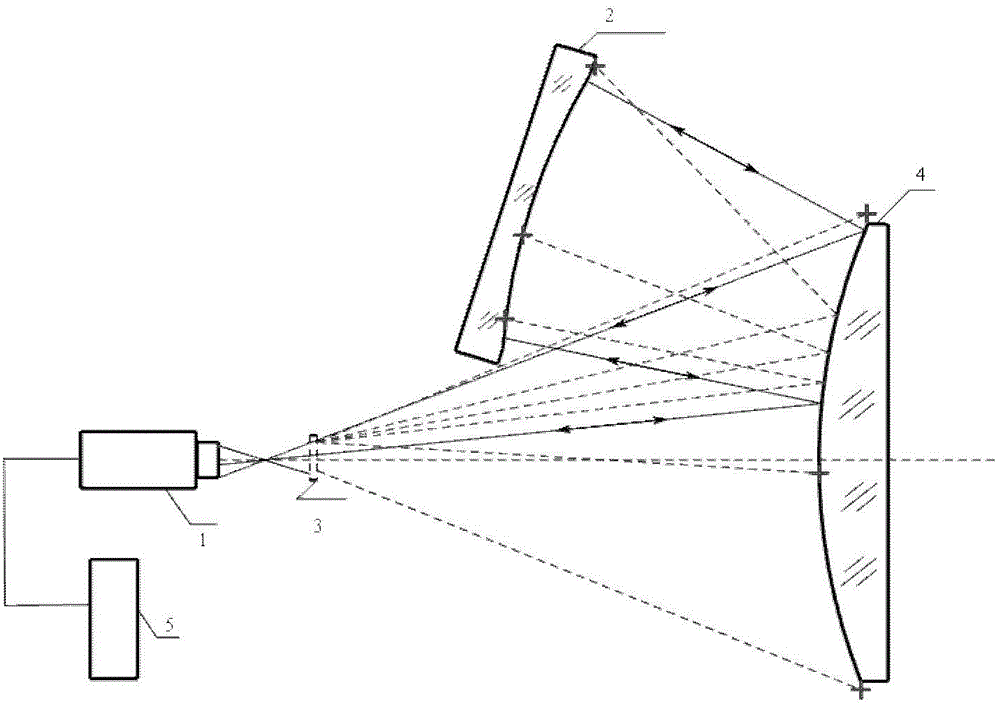
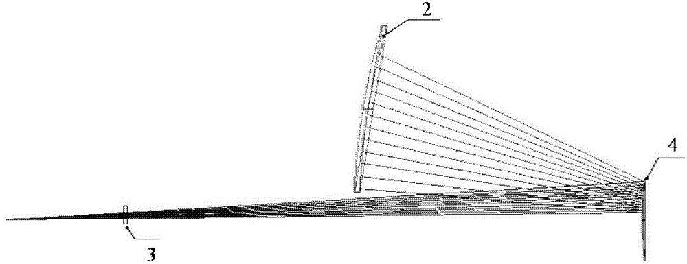
[0028] figure 1 As shown, a large-diameter convex high-order aspheric surface detection method in this embodiment includes a phase-shift interferometer 1, an auxiliary spherical mirror 2, a calculation hologram 3 and a computer system 5, and the measured optical element is a large-diameter convex high-order aspheric surface. The optical element of the sub-aspheric surface 4, the computer 5 is connected with the phase-shift interferometer 1, and the front focus of the optical system composed of the hologram 3 and the measured large-aperture convex high-order aspheric surface 4 and the focus of light waves emitted by the phase-shift interferometer 1 are calculated. Coincident, the rear focal point coincides with the spheric...


PUM


Abstract

The invention relates to a system for detecting a large-aperture and high-order convex aspheric surface. The system comprises a phase shift interferometer, an auxiliary spherical reflector, a computer-generated hologram and a computer, wherein the computer is connected with the phase shift interferometer; a front focal point of an optical system comprising the computer-generated hologram and the high-order convex aspheric surface and a focal point of an optical wave sent by the phase shift interferometer coincide, and a rear focal point and a sphere center of the auxiliary spherical reflector coincide; after the optical wave sent by the phase shift interferometer passes through the computer-generated hologram, the optical wave is reflected by the high-order convex aspheric surface and becomes a standard spherical wave; after the standard spherical wave is reflected by the auxiliary spherical reflector, the standard spherical wave goes back in the same way to the phase shift interferometer, so that subaperture zero-crossing detection of the area corresponding to the high-order convex aspheric surface is realized; the phase shift interferometer obtains a subdomain, having overlapping areas, on the high-order convex aspheric surface; and a data processing unit in the computer processes data in the subdomain, and full-aperture surface-shaped distribution information of the high-order convex aspheric surface is obtained. The invention further provides a device for detecting a convex spherical mirror or a convex aspherical mirror.

Description

technical field [0001] The invention belongs to the field of advanced optical manufacturing and detection, and relates to an optical detection method, in particular to a large-diameter convex high-order aspheric surface detection method. technical background [0002] Compared with traditional optical spherical surfaces, aspheric surfaces have great advantages in correcting aberrations. Often, one aspheric lens can replace the role of multiple spherical lenses, which greatly reduces the number and weight of the entire optical system unit. For example, the United States in this century In the "National Ignition Facility" NIF (National Ignition Facility) proposed at the beginning, large-aperture aspheric surfaces have a relatively large application proportion; the development of space optics, astronomy and other disciplines is increasingly dependent on large-aperture optical equipment, and large-aperture aspheric surfaces Spherical elements have become key components for suppor...

Claims


Application Information

Patent Timeline
Patent Type & Authority Applications(China)
IPC IPC(8): G01B11/24
CPCG01B9/02039G01B9/02085G01B11/2441G01M11/005
Inventor 范斌闫锋涛侯溪陈强万勇建伍凡
Owner INST OF OPTICS & ELECTRONICS - CHINESE ACAD OF SCI
Why Eureka
Try Eureka