Zero-magnetic flux current transformer capable of preventing electricity from being stolen through high-intensity magnetic field

A current transformer, zero-flux technology, applied in the direction of inductor, transformer/inductor shell, transformer/inductor coil/winding/connection, etc., can solve the problem of low measurement accuracy of current transformer and no anti-theft function , the problem of high production cost, to achieve the effect of convenient design and use, enhanced insulation, and improved measurement accuracy

Inactive Publication Date: 2013-10-02
HEBEI SHENKE ELECTRONICS CO LTD
View PDF2 Cites 6 Cited by
  • Summary
  • Abstract
  • Description
  • Claims
  • Application Information

AI Technical Summary

Problems solved by technology

[0005] The purpose of this invention is to solve the technical problems of the existing current transformers, such as too low measurement accuracy, too large volume, too high production cost, and no anti-stealing function. In order to solve this problem, we have designed an anti-strong The zero-flux current transformer for magnetic field stealing electricity is easy to use, and the case made of cold-rol

Method used


Image

  • Zero-magnetic flux current transformer capable of preventing electricity from being stolen through high-intensity magnetic field
  • Zero-magnetic flux current transformer capable of preventing electricity from being stolen through high-intensity magnetic field
  • Zero-magnetic flux current transformer capable of preventing electricity from being stolen through high-intensity magnetic field

Examples


Embodiment Construction

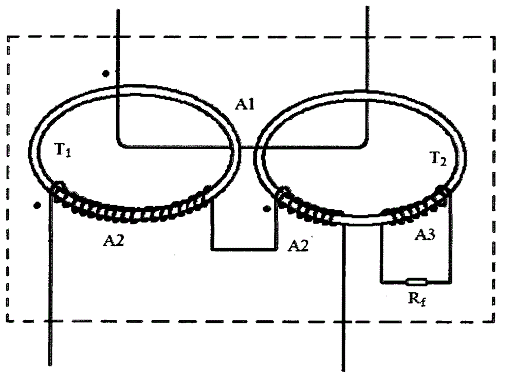
[0010] A zero-flux current transformer capable of preventing electricity theft by a strong magnetic field, including a casing, the key point is that the current transformer also includes a first annular iron core T arranged in the casing 1 , the second ring core T 2 , the primary winding A1, the secondary winding, the additional winding A3 and the compensation resistor R connected to both ends of the additional winding A3 f , the primary winding A1 passes through the first toroidal core T in turn 1 , the second ring core T 2 Each N 1 turns, or pass through the first toroidal core T at the same time 1 , the second ring core T 2 Total N 1 turns, the secondary winding includes successively passing through the first toroidal core T 1 , the second ring core T 2 The first secondary winding A2 and the second secondary winding A2', the coil turns of the first secondary winding A2 and the second secondary winding A2' are N respectively 2 and N 2 ’, the additional winding A3 pa...


PUM


Abstract

The invention provides a zero-magnetic flux current transformer capable of preventing electricity from being stolen through a high-intensity magnetic field. The zero-magnetic flux current transformer comprises a case and further comprises a first annular iron core, a second annular iron core, a primary winding, a secondary winding, an additional winding and compensation resistors connected to the two ends of the additional winding, wherein the first annular iron core, the second annular iron core, the primary winding, the secondary winding, the additional winding and the compensation resistors are arranged in the case. The compensation resistors meet the formula that N2:N2':N3=1: (1/3-1): (1/3-1). The zero-magnetic flux current transformer has the advantages that the case made of cold-roll steel sheets or electrical pure iron or permalloy or silicon steel can be used for effectively preventing the situation that electricity is stolen through the high-intensity magnetic field; through the combination of magnetic shunt compensation and potential compensation, the requirement that errors are in the levels of 0.02, 0.01 and 0.005 can be met, therefore, the measurement accuracy is improved, the size of the iron cores is reduced, and production cost is lowered. A plastic insulating layer can be used for playing a good role in insulation reinforcement and moist resistance.

Description

technical field [0001] The invention belongs to the technical field of current measurement, and relates to a current transformer, in particular to a zero-flux current transformer capable of preventing electricity theft by a strong magnetic field. Background technique [0002] Ordinary current transformers used in the field of electrical measurement usually use a single iron core on which a considerable number of enameled wires are wound to achieve the required current and measurement accuracy, especially the miniature current transformers for instruments. Its volume is very small, and the highest measurement accuracy level that a single iron core can achieve is currently 0.05. For example, a 0.05 level 1.5(6)A / 5mA current transformer uses a 16 / 21×10 iron core, the performance requirement is 10mA≥0.45mV, the secondary winding is 2400 turns, and the primary winding is 8 turns, in order to achieve JJG313-2010 to 0.05 Grade requirements, this core is very difficult to produce a...

Claims


Application Information

Patent Timeline
IPC IPC(8): H01F38/30H01F27/30H01F27/40H01F27/02
Inventor 冯长泳王彦硕王力崇胡文亭和鹏陈双平王少华耿赛强寅成
Owner HEBEI SHENKE ELECTRONICS CO LTD
Why Eureka
Try Eureka