Dynamic reactive compensation mounting point optimization method for multi-direct-current centralized infeed receiving end power grid

A technology of receiving-end power grid and optimization method, applied in reactive power compensation, reactive power adjustment/elimination/compensation and other directions

Active Publication Date: 2013-10-02
STATE GRID CORP OF CHINA +1
View PDF6 Cites 26 Cited by
  • Summary
  • Abstract
  • Description
  • Claims
  • Application Information

AI Technical Summary

Problems solved by technology

In addition, there is a saturation point in the dynamic reactive power compensation point to improve the recovery speed of multiple DC centralized feed-in receiving end grids

Method used


Image

  • Dynamic reactive compensation mounting point optimization method for multi-direct-current centralized infeed receiving end power grid
  • Dynamic reactive compensation mounting point optimization method for multi-direct-current centralized infeed receiving end power grid
  • Dynamic reactive compensation mounting point optimization method for multi-direct-current centralized infeed receiving end power grid

Examples


Embodiment

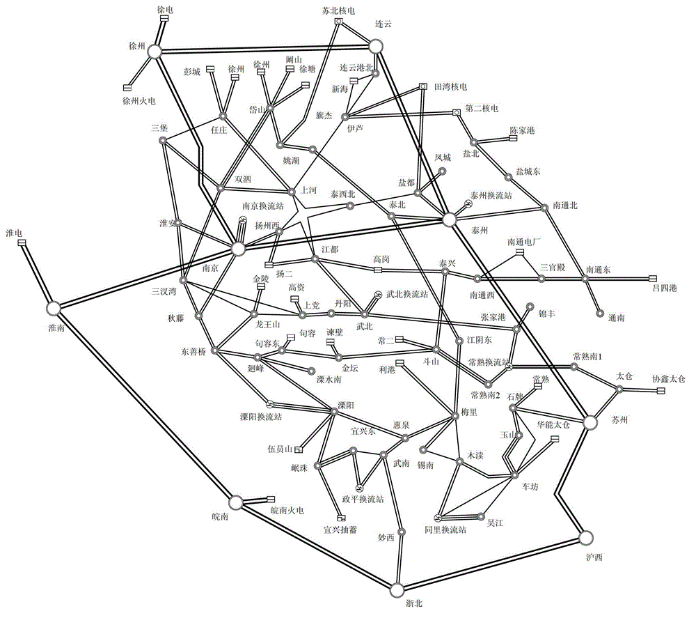
[0094] In the embodiment of the present invention, the planning diagram of Jiangsu 500 kV and above power grid in 2020 is as follows figure 1 shown. by figure 1 The Jiangsu 2020 planned power grid shown is the analysis object.

[0095] According to the plan, by 2020, Jiangsu Power Grid plans to feed into DC 7 times, as shown in Table 1. Among them, the 1st-2nd rounds of DC are built and put into operation, and the 4th-7th rounds of DC are planned and constructed DCs. Jiangsu Power Grid will become a typical multi-DC centralized feed-in area.

[0096] Table 1 Jiangsu's 2020 planning feed-in DC table

[0097]

[0098]

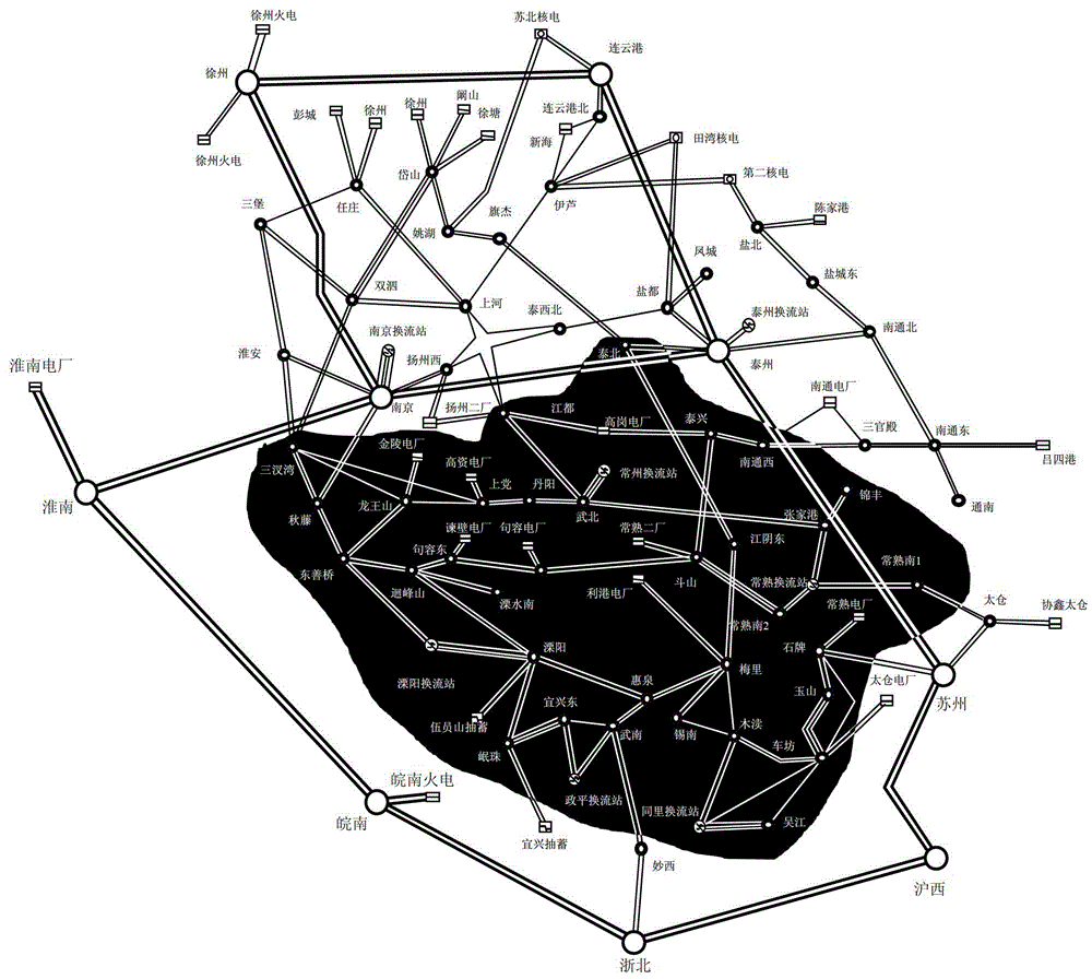
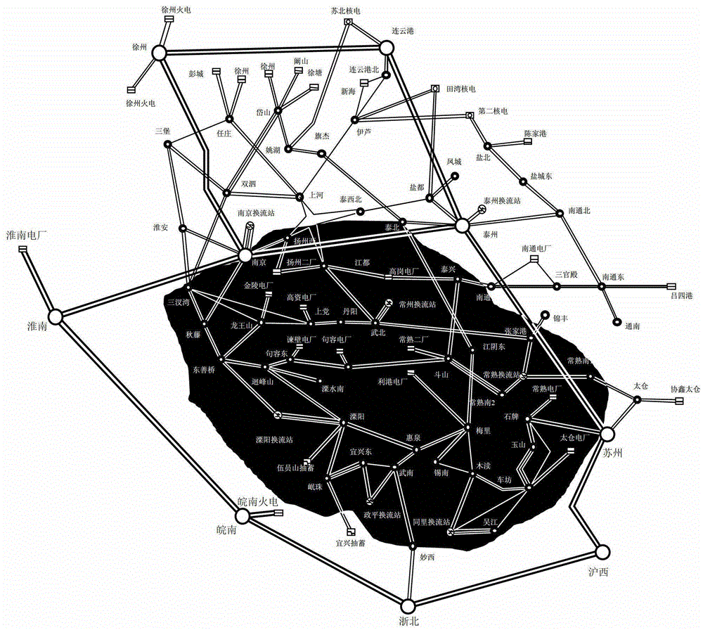
[0099] In this area, the Xixinan-Liyang, Xuzhou-Nanjing, Zhebei-Zhezhong lines were selected as typical lines inside and outside the area, and PSD-BPA software was used to carry out the simulation calculation of three-phase permanent short-circuit faults for the above three-circuit lines , after the calculation is completed, with the geographic wiring d...


PUM


Abstract

The invention relates to a dynamic reactive compensation mounting point optimization method for a multi-direct-current centralized infeed receiving end power grid. According to the method, a simulated computation of a dynamic voltage change process is demonstrated in a graphical way. The method comprises the following steps: excavating a voltage stability weak region in a multi-infeed direct-current receiving end area; performing voltage response computation under point-by-point reactive change on alternating-current and direct-current nodes in the weak region by adopting a transient stability computation procedure for a power system; establishing a direct-current weight coefficient model by taking direct-current impedance and direct-current rated volume as parameter factors according to direct-current mutual influences, combining with a corresponding voltage computation result, computing the reactive node investment effect indexes of the weak region, and sequencing according to the indexes; and mounting a dynamic reactive compensation device on the node at a first order, sequencing once again, and repeatedly circulating till the required quantity of sequencing mounting points is satisfied. A final result is the node sequence of dynamic reactive compensation mounting, appropriate cost of the power grid is ensured, and the voltage stability of the multi-direct-current centralized infeed receiving end power grid is improved.

Description

technical field [0001] The invention relates to the technical field of power systems, in particular to a method for optimizing installation points of dynamic reactive power compensation in which multiple direct currents are centrally fed into a receiving-end power grid. Background technique [0002] It is a typical feature of the future receiving-end power grid that multiple DCs are fed into the same receiving area at the same time. For example, the Yangtze River Delta, Pearl River Delta and other regions will have multiple DC feeds at the same time in the future. The biggest risk faced by multi-DC feed-in and receiving-end grids is the problem of voltage stability. Once the scale of DC feed-in is too large and concentrated, the failure of the AC system may cause the voltage to collapse. [0003] According to the practical experience of power grids at home and abroad, installing dynamic reactive power compensation is an effective means to improve voltage stability. Consider...

Claims


Application Information

Patent Timeline
Patent Type & Authority Applications(China)
IPC IPC(8): H02J3/18
CPCY02E40/30
Inventor 周勤勇张彦涛贺海磊
Owner STATE GRID CORP OF CHINA
Why Eureka
Try Eureka