

Light-emitting module and lamp using same
A light-emitting module and light-emitting element technology, which is applied to optical elements for changing the spectral characteristics of emitted light, semiconductor devices of light-emitting elements, light sources, etc., can solve problems such as light output reduction, improve design freedom, and suppress extraction Efficiency reduction effect
- Summary
- Abstract
- Description
- Claims
- Application Information
AI Technical Summary
Problems solved by technology
Method used
Image

Examples
Embodiment approach 1
[0042] Overall composition
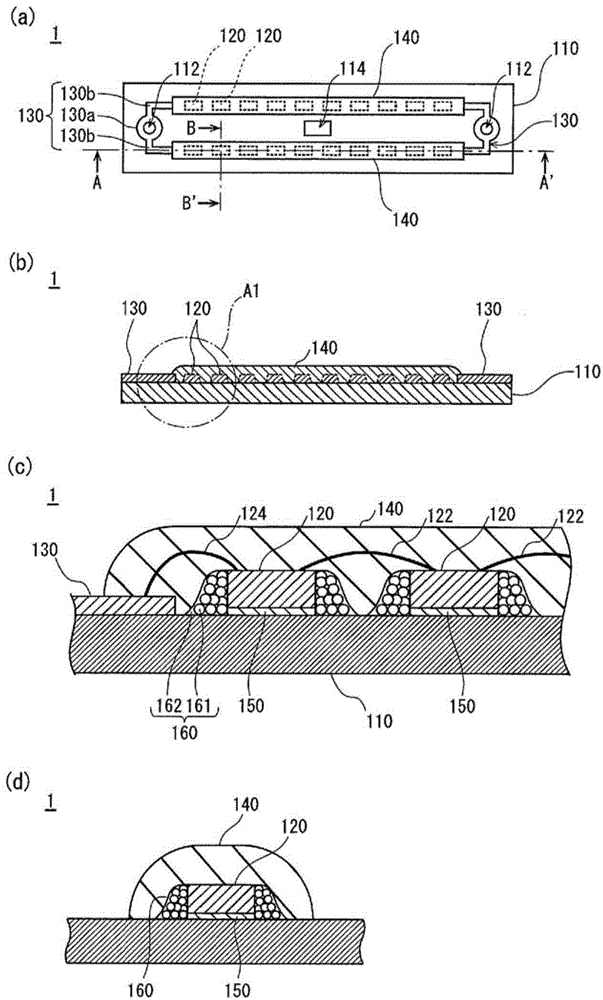
[0043] figure 1 (a) is a plan view of the light emitting module 1 of this embodiment. figure 1 (b) is viewed from the direction of the arrow figure 1 In the figure of the section cut along the line A-A', figure 1 (c) is the figure 1 (b) Enlarged cross-sectional view of the area surrounded by the dot-dash line A1.
[0044] like figure 1 As shown in (a), the light emitting module 1 includes a substrate 110 , a plurality of LED chips (semiconductor light emitting elements) 120 arranged in two rows on the substrate 110 , a wiring pattern 130 for supplying power to the LED chips 120 , and The sealing member 140 collectively seals a plurality of LED chips 120 for each row. In addition, if figure 1 As shown in (c), the light emitting module 1 has a chip mounting member 150 for bonding the LED chip 120 to the substrate 110 and a heat transfer member 160 for dissipating heat generated by the LED chip 120 to the substrate 110 .
[0045] Substrate ...
Embodiment approach 2
[0115] Hereinafter, the structure of the light emitting module 2 of this embodiment is demonstrated.
[0116] Figure 7 is a partial sectional view of the light emitting module 2 .
[0117] like Figure 7 As shown, the light-emitting module 2 has substantially the same configuration as the light-emitting module 1 of Embodiment 1. The difference from Embodiment 1 is that the heat transfer member 260 does not contain fine particles 161 but is composed of a single nanocomposite material. Therefore, in this embodiment, the heat transfer member 260 will be described. In addition, the same code|symbol is attached|subjected to the same structure as Embodiment 1, and description is abbreviate|omitted suitably.
[0118] The heat transfer member 260 has the function of dissipating the heat generated by the LED chip 120 to the substrate 110 as in the first embodiment. like Figure 7 As shown, the heat transfer member 260 is arranged between the four side surfaces of the outer periph...
Embodiment approach 3
[0137] Hereinafter, the structure of the light emitting module 1001 of this embodiment is demonstrated. In addition, the same code|symbol is attached|subjected to the same structure as Embodiment 1, and description is abbreviate|omitted suitably.
[0138] Figure 9 The light emitting module of this embodiment is shown, (a) is a plan view, (b) is a plan view of the state which removed the sealing member from the area enclosed by the dashed-dotted line A2 in (a), (c) is a partial cross-sectional view.
[0139] like Figure 9As shown in (a) to (c), the light emitting module 1001 includes a substrate 1110 , a plurality of LED chips 120 , a sealing member 1140 , and a plurality of heat transfer members 160 arranged in the outer peripheral regions of the plurality of LED chips 120 .
[0140] The substrate 1110 is formed in a rectangular plate shape, a wiring pattern is formed on one surface, and a circular ring-shaped frame 1118 in a planar view is arranged at a substantially cent...
PUM
| Property | Measurement | Unit |
|---|---|---|
| particle size | aaaaa | aaaaa |
| particle size | aaaaa | aaaaa |
| thermal conductivity | aaaaa | aaaaa |
Abstract
Description
Claims
Application Information