Battery housing structure
A technology for accommodating structures and batteries, which is applied to batteries, secondary batteries, structural parts, etc. It can solve the problems of electrode terminal deterioration and easy temperature rise around electrode terminals, etc., to reduce thermal resistance, improve redundancy, and improve uniformity Effect
- Summary
- Abstract
- Description
- Claims
- Application Information
AI Technical Summary
Problems solved by technology
Method used
Image
Examples
no. 1 approach
[0040] (Outline of battery housing structure)
[0041] The first embodiment relates to a battery housing structure of a power storage device. The battery housing structure of the first embodiment is preferably combined with components such as a bidirectional converter, a transformer, and a control circuit to form a power storage device. The power storage device is preferably connected to the power system for regulating the supply and demand of power. The battery housing structure of the first embodiment may be combined with other components to form devices other than the power storage device.
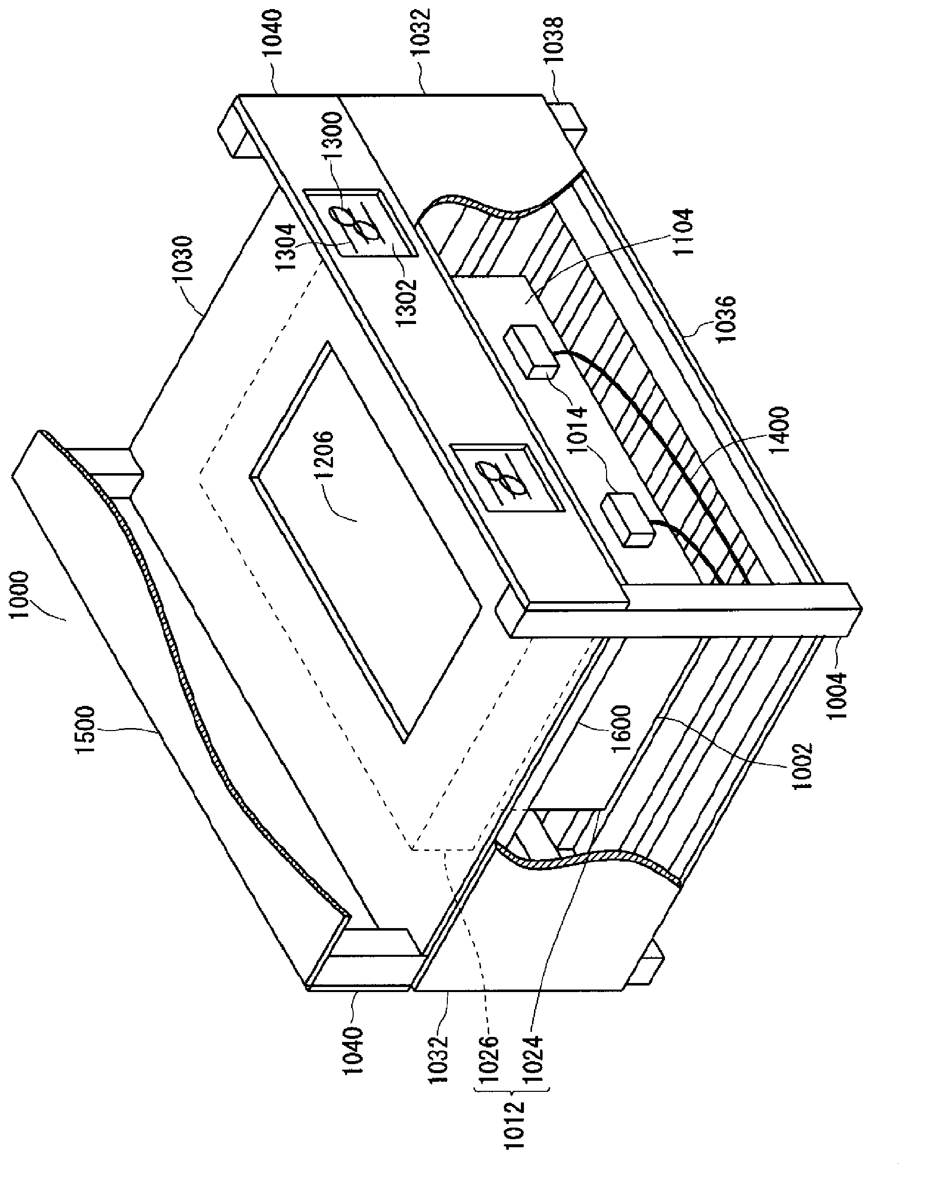
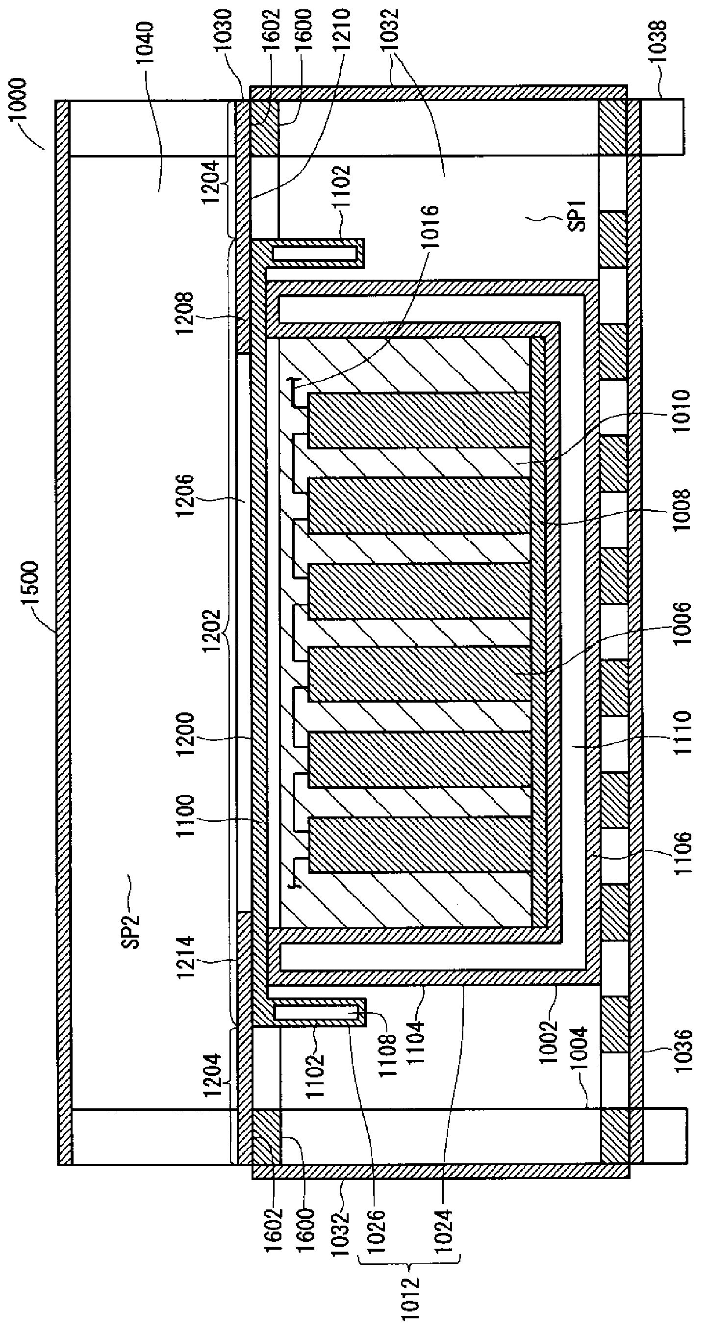
[0042] figure 1 and figure 2 is a schematic diagram of the battery housing structure of the first embodiment. figure 1 is a stereogram, figure 2 is a sectional view.
[0043] In the battery containing structure 1000 of the first embodiment, as figure 1 and figure 2 As shown, modular batteries 1002 are housed in modular battery holders 1004 . The module battery 1002 may also ...
no. 2 approach
[0076] (Outline of battery housing structure)
[0077] The second embodiment relates to a battery containing structure used instead of the battery containing structure of the first embodiment.
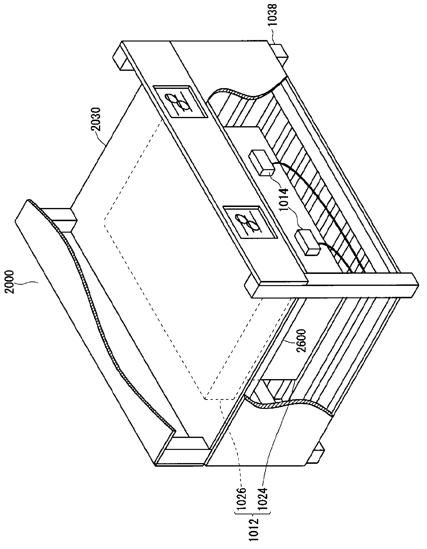
[0078] image 3 and Figure 4 is a schematic diagram of the battery housing structure of the second embodiment. image 3 is a stereogram, Figure 4 is a sectional view.
[0079] The battery containing structure 2000 of the second embodiment is as image 3 , Figure 4 As shown, it is the same as the battery containing structure 1000 of the first embodiment except that the top plate 1030 formed with the opening 1206 is replaced with the top plate 2030 formed with no opening 1206 . Therefore, in the description of the second embodiment, the same components as those of the first embodiment are given the same reference numerals as those of the first embodiment, and the points different from the first embodiment will be mainly described. The description of the first embodiment applies...
no. 3 approach
[0086] (Outline of battery housing structure)
[0087] The third embodiment relates to a battery containing structure used instead of the battery containing structure of the first embodiment.
[0088] Figure 5 and Figure 6 is a schematic diagram of the battery containing structure of the third embodiment. Figure 5 is a stereogram, Figure 6 is a sectional view.
[0089] The battery accommodating structure 3000 of the third embodiment is the same as the battery accommodating structure 1000 of the first embodiment except that the top plate 3030 forming the opening 1206 is replaced by the top plate 3030 not forming the opening, and the top wall 3100 A heat transfer medium 3700 is interposed between the first portion 3202 of the top plate 3030 , and the top wall 1100 with a flat outer surface 1200 is replaced by a top wall 3100 formed with reinforcing ribs 3702 . Therefore, in the description of the third embodiment, the same components as those of the first embodiment are...
PUM
 Abstract
Description
Claims
Application Information
 - R&D
- Intellectual Property
- Life Sciences
- Materials
- Tech Scout
- Unparalleled Data Quality
- Higher Quality Content
- 60% Fewer Hallucinations
Browse by: Latest US Patents, China's latest patents, Technical Efficacy Thesaurus, Application Domain, Technology Topic, Popular Technical Reports.
© 2025 PatSnap. All rights reserved.Legal|Privacy policy|Modern Slavery Act Transparency Statement|Sitemap|About US| Contact US: help@patsnap.com


