Encircling LED road bridge handrail lamp

A railing light and enveloping technology, which is applied in the direction of lighting devices, light sources, fixed lighting devices, etc., can solve the problems of reducing the rigidity of the guardrail, high cost, and the influence of heat dissipation of the lamps, etc., to ensure consistency, simple manufacturing process, and on-site installation simple and easy effects

Active Publication Date: 2013-10-09
广东迪艾生光电技术有限公司
View PDF6 Cites 2 Cited by
  • Summary
  • Abstract
  • Description
  • Claims
  • Application Information

AI Technical Summary

Problems solved by technology

[0003] 1. The light source is far too concentrated, which will produce serious glare pollution;
[0004] 2. The uniformity of illumination on the bridge road surface is very poor;
[0005] 3. It is difficult to maintain lamps and lanterns, the cost is high, and the area is large;
[0006] 4. The distance between the high pole light source and the illuminated bridge deck is too far, most of the light is lost in the air, and the light utilization rate is low, resulting in energy waste
[0014] 1. The heat dissipation body of the lamp is inside the guardrail tube, the air convection is very poor, and the heat dissipation of the lamp is affected to a certain extent;
[0015] 2. The opening of the guardrail pipe is too large, which seriously reduces the rigidity of the guardrail and seriously weakens the safety protection performance of the guardrail;
[0016] 3. The junction between the guardrail and the lamp body is not easy to be completely bridged. On the one hand, it affects the appearance, on the other hand, it is not easy to do waterproofing, and the inside of the tube and the lamp body are easy to enter water, which is not good for the internal power supply, cables and lamp beads;
[0017] 4. The structure of the lamp body is complex and the cost is high;
[0019] 6. It is almost impossible to implement the transformation of existing bridge guardrail lamps, because it is impossible to cut guardrail tubes on site

Method used


Image

  • Encircling LED road bridge handrail lamp
  • Encircling LED road bridge handrail lamp
  • Encircling LED road bridge handrail lamp

Examples


Embodiment Construction

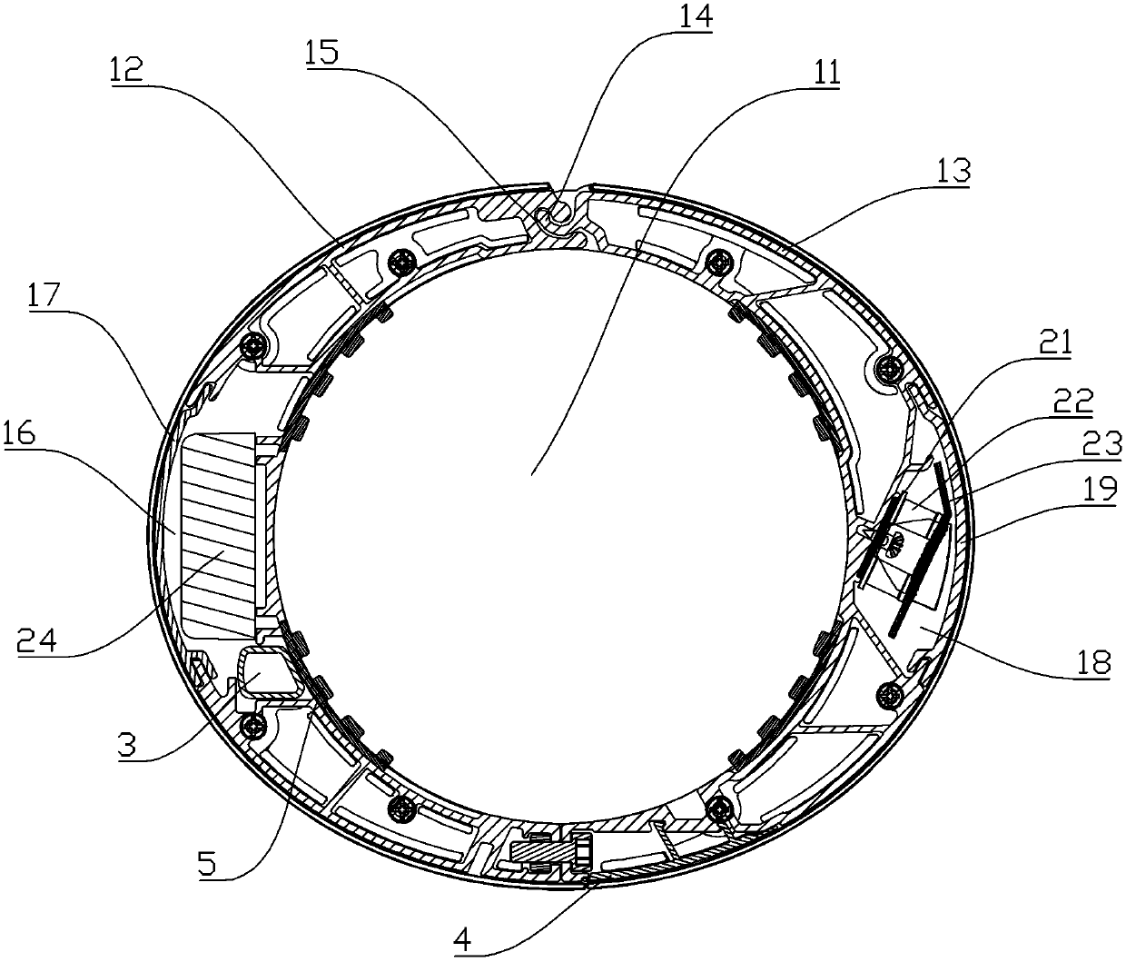
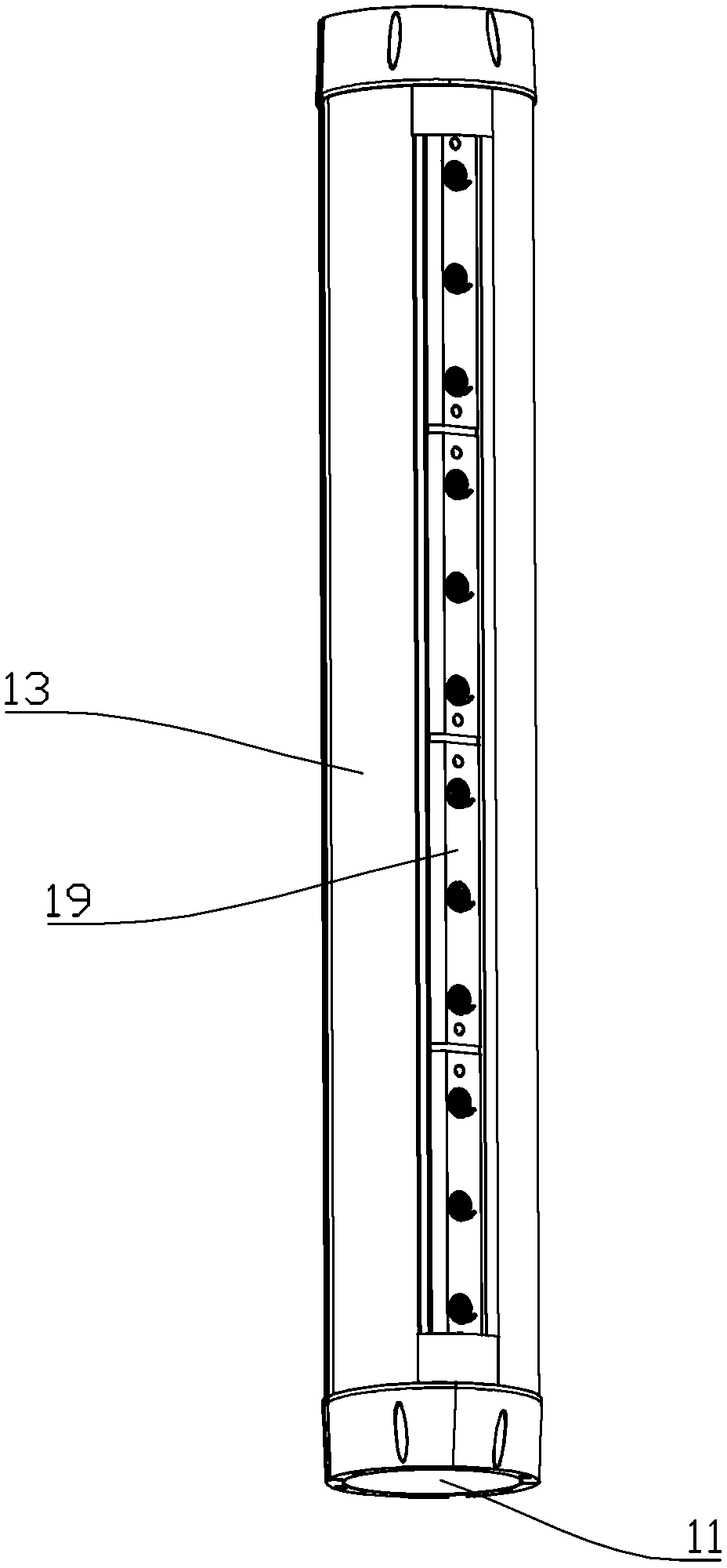
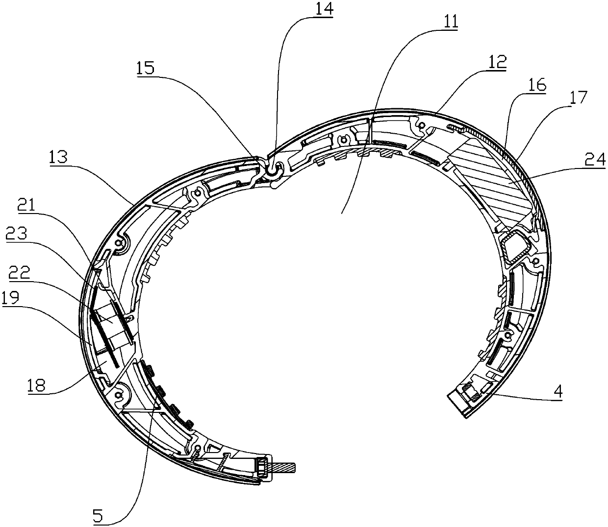
[0037] refer to Figure 1 ~ Figure 3 , the present invention is an enveloping LED road and bridge railing light, comprising: a cylindrical shell, which can be fixedly installed on the guardrail, and its inner cavity 11 matches the shape of the guardrail; LED components are installed in the cylindrical shell. The cylindrical shell includes a first shell 12 and a second shell 13, one end of the first shell 12 and the second shell 13 are pivotally connected together by a connecting device, and the other end is fixedly connected by a bolt. The connecting device includes an arc-shaped hook 14 arranged at the end of the second shell 13 and an arc-shaped hole 15 arranged at the end of the first shell 12 to cooperate with the arc-shaped hook 14, the first shell 12 and the second The screw connections of the housing 13 are covered by a decorative cover 4 . By setting the cylindrical shell as an independent first shell 12 and second shell 13, firstly insert the arc-shaped hook 14 on th...


PUM


Abstract

The invention discloses an encircling LED road bridge handrail lamp which comprises a tube-shaped outer shell and an LED assembly. The tube-shaped outer shell can be fixedly installed on a handrail, and an inner cavity of the tube-shaped outer shell is matched with the handrail in shape. The LED assembly is installed inside the tube-shaped outer shell. The tube-shaped outer shell comprises a first outer shell and a second outer shell. One end of the first outer shell and one end of the second outer shell are connected together through a connecting device in a pivoting mode, and the other end of the first outer shell and the other end of the second outer shell are fixedly connected through a bolt. The connecting device comprises a circular-arc-shaped clamping hook and a circular-arc-shaped clamping hole, wherein the circular-arc-shaped clamping hook is arranged at the end of the second outer shell, and the circular-arc-shaped clamping hole is formed in the end of the first outer shell and matched with the circular-arc-shaped clamping hook. The encircling LED road bridge handrail lamp is independent of the handrail, in other words, only the LED road bridge handrail lamp needs to be provided, and the handrail needs not to be manufactured. Therefore, different installation requirements of an old bridge and a new bridge can be met at the same time. The encircling LED road bridge handrail lamp is easy to install on site, and meanwhile uniformity of the installation angle of the LED road bridge handrail lamp is easy to ensure. After the LED road bridge handrail lamp is installed, influences on the appearance of the handrail are minimized and the manufacturing technology is simple.

Description

technical field [0001] The invention relates to an encircling LED road and bridge railing light. Background technique [0002] With the development of China's economy and the policy trend of promoting urbanization, the scale and density of urban overpasses have become larger and larger, and the demand for bridge lighting lamps has also increased rapidly. In urban bridge road lighting, the traditional solution is to use high pole lights as lighting fixtures. But high pole lights have the following disadvantages: [0003] 1. The light source is far too concentrated, which will produce serious glare pollution; [0004] 2. The uniformity of illumination on the bridge road surface is very poor; [0005] 3. It is difficult to maintain lamps and lanterns, the cost is high, and the area is large; [0006] 4. The distance between the high pole light source and the illuminated bridge deck is too far, most of the light is lost in the air, and the light utilization rate is low, resu...

Claims


Application Information

Patent Timeline
Patent Type & Authority Applications(China)
IPC IPC(8): F21S8/00F21V19/00F21W111/08F21Y101/02
Inventor 周玉龙李晓成
Owner 广东迪艾生光电技术有限公司
Why Eureka
Try Eureka