Display device and manufacturing method thereof

A technology for display devices and light guide plates, which is applied to lighting devices, fixed lighting devices, components of lighting devices, etc. It can solve the problems of widening the frame and achieve the effects of reducing width, improving utilization rate, and shortening the light mixing distance

Active Publication Date: 2013-10-09
TCL CHINA STAR OPTOELECTRONICS TECH CO LTD
View PDF6 Cites 0 Cited by
  • Summary
  • Abstract
  • Description
  • Claims
  • Application Information

AI Technical Summary

Problems solved by technology

[0004] However, in the existing technology, no matter what measures are taken, there will always be a light mixing distance, and considering the geometric dimensions of optical lenses and microstructures, it will lead to wider borders

Method used


Image

  • Display device and manufacturing method thereof
  • Display device and manufacturing method thereof
  • Display device and manufacturing method thereof

Examples


Embodiment Construction

[0026] Hereinafter, the present invention will be described in detail with reference to the accompanying drawings.

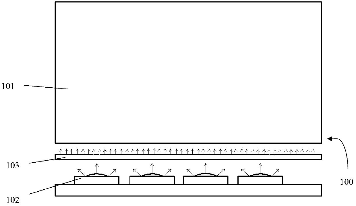
[0027] figure 1 The main structure of the display device 100 according to the present invention is schematically shown.

[0028] The display device 100 includes a light guide plate 101 for guiding the light path, a light emitting element 102 located on one side of the light guide plate 101 , and a light mixing unit 103 located between the light guide plate 101 and the light emitting element 102 .

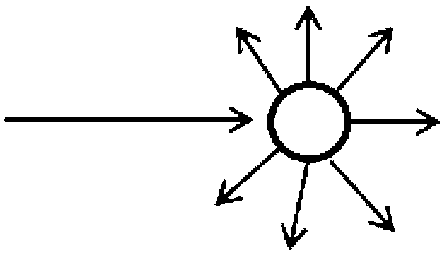
[0029] The light mixing unit 103 can make the light from the light emitting element 102 take place in one or more of scattering, refraction and diffusion (see figure 2 ), thereby greatly changing the propagation path of the light emitted by the light emitting element 102, and finally reducing the light mixing distance of the light emitting element 102 (that is, the distance at which the uneven light source of the light emitting element 102 is mixed into a uniform su...


PUM


Abstract

The invention provides a display device and a corresponding manufacturing method thereof, and belongs to the technical field of panel display. The display device comprises a light guide plate, a light-emitting component and a light mixing unit, wherein the light-emitting component is placed on one side of the light guide plate, and the lighting mixing unit is placed between the light guide plate and the light-emitting component. The lighting mixing unit comprises a transparent sealed container and lighting mixing media, and the container is filled with the lighting mixing media, wherein the light mixing unit enables light from the light-emitting component to generate one or more of scattering, refraction and diffusion. By means of the display device and the manufacturing method thereof, the light mixing distance of the light-emitting component can be shortened, and narrow frame display can be achieved.

Description

technical field [0001] The present invention relates to a display device and a manufacturing method thereof, in particular to a display device including a light mixing unit and a manufacturing method thereof. Background technique [0002] Narrow bezel display is a development direction of display devices at present. In addition to the geometric dimensions of each component, the most important factor restricting narrow frame display is the light mixing distance, that is, the distance at which point light sources of LEDs are mixed into a uniform surface light source. [0003] In order to reduce the light mixing distance, the commonly used means in the prior art is to reduce the distance between the light-emitting diodes; The surface is covered with optical lenses to change the propagation path of light. [0004] However, in the prior art, no matter what measures are taken, a light mixing distance is always required, and considering the geometric dimensions of the optical len...

Claims


Application Information

Patent Timeline
Patent Type & Authority Applications(China)
IPC IPC(8): F21S8/00F21V5/00
CPCG02B6/0041Y10T29/49826G02B6/0025G02B6/0065G02B6/0023G02B6/0031
Inventor 张田
Owner TCL CHINA STAR OPTOELECTRONICS TECH CO LTD
Why Eureka
Try Eureka