Refractive correction AR display device and wearable AR equipment

A display device and projection device technology, applied in optics, optical components, instruments, etc., can solve the problems of improving imaging quality and optical performance, high system performance requirements, and limited system volume, so as to reduce the number of lenses and improve optical performance , high-definition effect

Pending Publication Date: 2019-08-23
BEIJING UNICORN TECH CO LTD
View PDF11 Cites 8 Cited by
  • Summary
  • Abstract
  • Description
  • Claims
  • Application Information

AI Technical Summary

Problems solved by technology

[0005] 1. The corrective lens is set between the beam splitter and the human eye. The structure is complex, the weight increases, and the optical surface brings more stray light and brightness loss. It requires a larger exit pupil distance to wear, and has high requirements for system performance.
[0006] 2. The volume of the system is limited, and it is difficult to improve the imaging quality and optical performance by increasing the number of lenses

Method used


Image

  • Refractive correction AR display device and wearable AR equipment
  • Refractive correction AR display device and wearable AR equipment
  • Refractive correction AR display device and wearable AR equipment

Examples


Embodiment 1

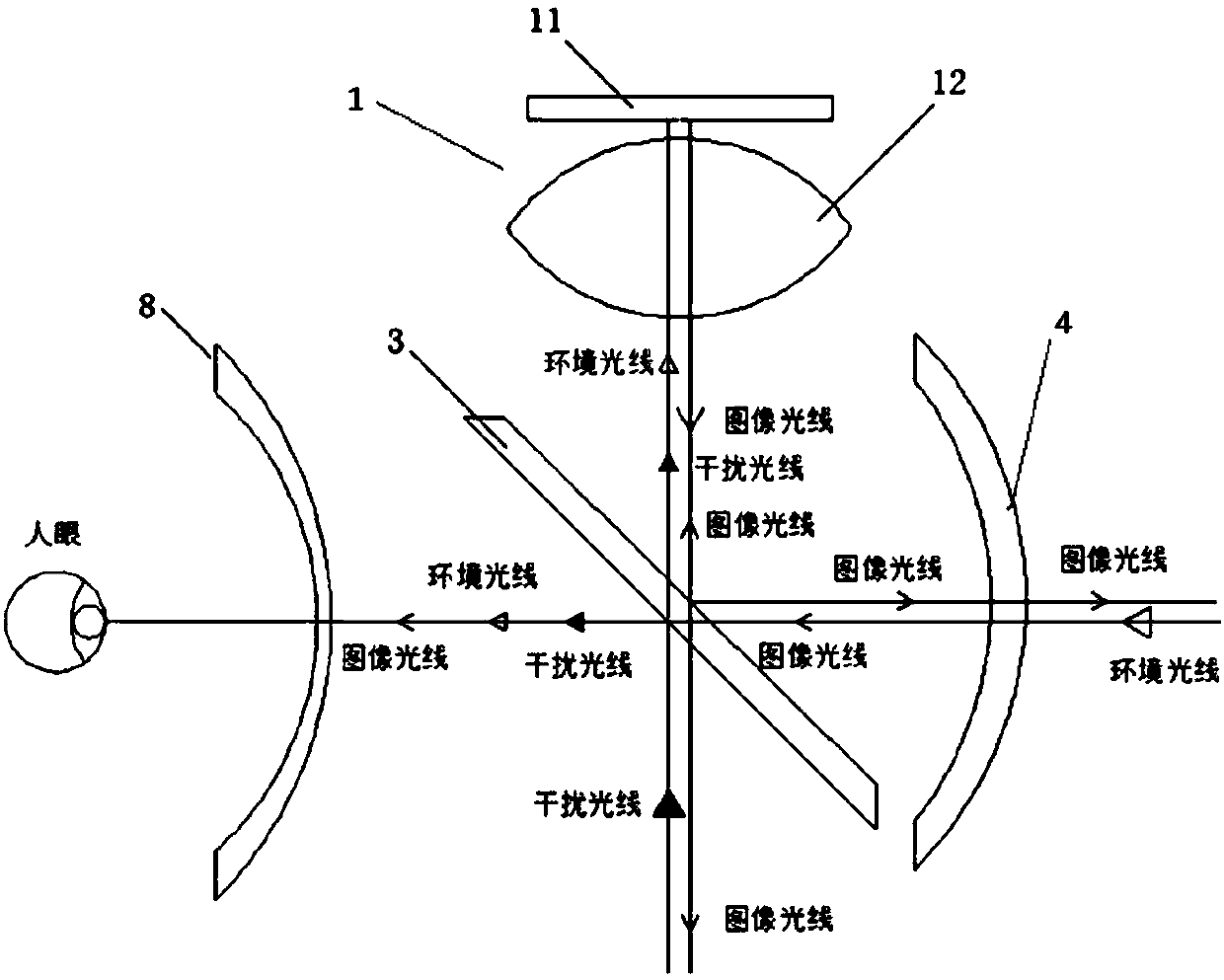
[0045] This embodiment provides an AR display device, such as figure 2 As shown, the AR display device includes an image projection device 1 and an optical path assembly;

[0046] The image projection device 1 includes an image source 11 and a lens 12 . It should be noted that the image projection device may also only include an image source. Wherein, the function of the image source 11 is to display images that need to be projected into human eyes, and the image source 11 can be a planar image source, including but not limited to an image source with integrated light sources or a single image source. For example, OLED (Organic Light-Emitting Diode, organic light-emitting diode), LCOS (Liquid Crystal On Silicon, liquid crystal on silicon), LCD (Liquid Crystal Display, liquid crystal display), MEMS (Microelectromechanical Systems, micro-electromechanical display system), DMD (Digital Micro-mirror Device, digital micromirror component) and other display principle electronic d...

Embodiment 2

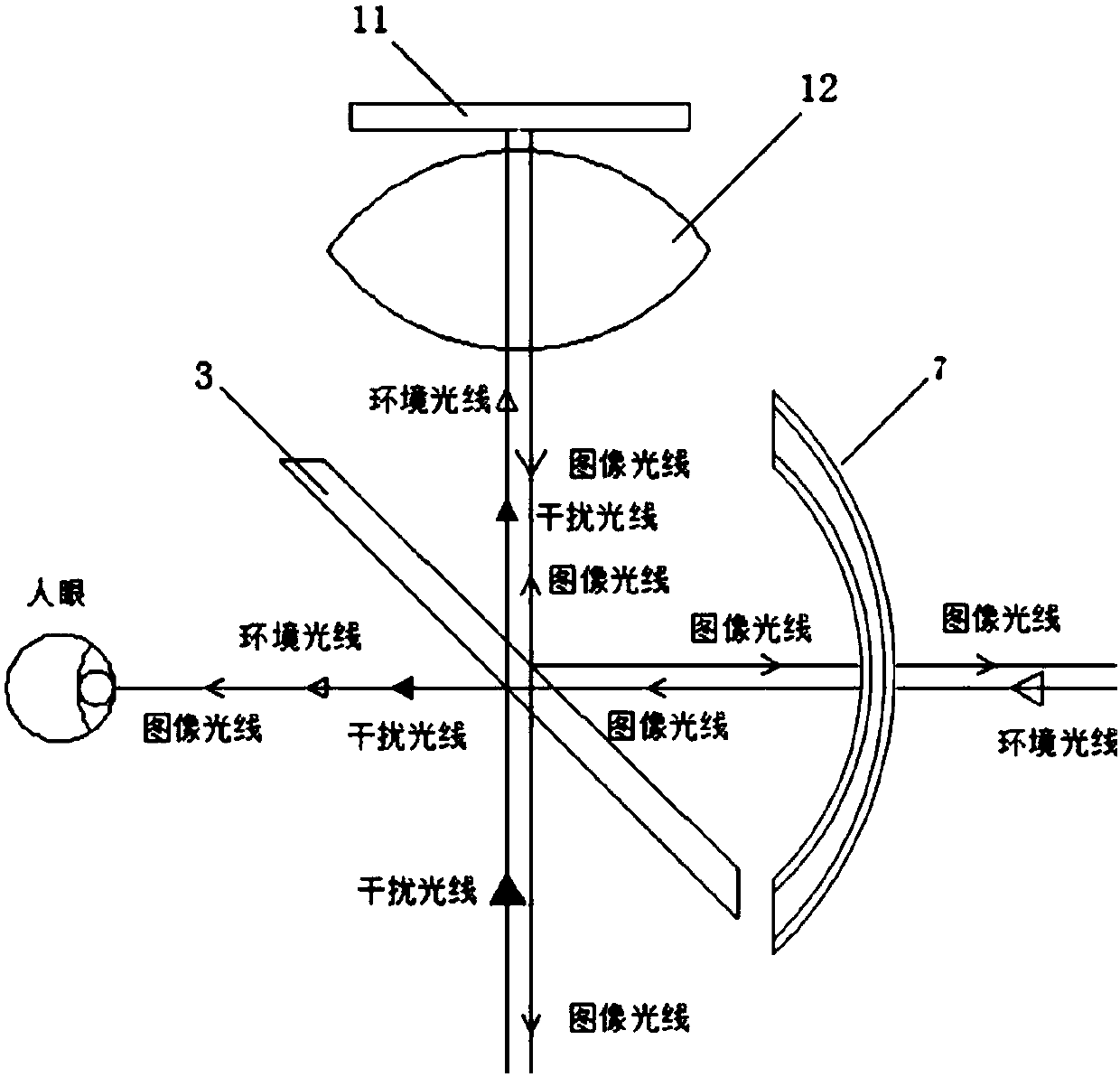
[0055] The image projection device 1 includes an image source 11 and a lens 12 . It should be noted that the image projection device may also only include an image source. Wherein, the function of the image source 11 is to display images that need to be projected into human eyes, and the image source 11 can be a planar image source, including but not limited to an image source with integrated light sources or a single image source. For example, OLED (Organic Light-Emitting Diode, organic light-emitting diode), LCOS (Liquid Crystal On Silicon, liquid crystal on silicon), LCD (Liquid Crystal Display, liquid crystal display), MEMS (Microelectromechanical Systems, micro-electromechanical display system), DMD (Digital Micro-mirror Device, digital micromirror component) and other display principle electronic devices. Among them, OLED and LCD are image sources of integrated light sources; LCOS, MEMS and DMD are single image sources, and additional auxiliary light sources are require...

Embodiment 3

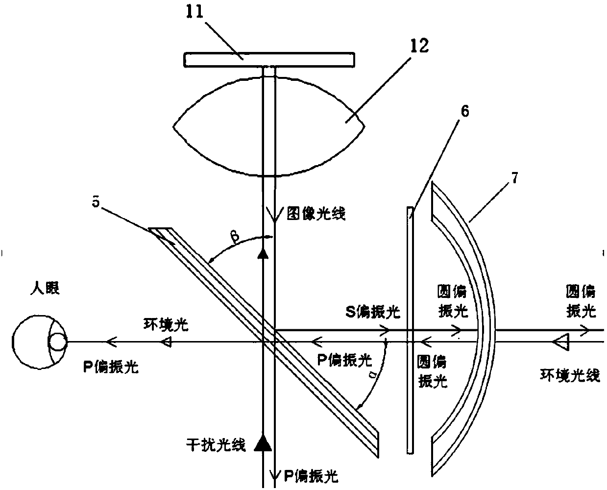
[0075] The wearable AR device of this embodiment is provided with the above-mentioned refraction correction AR display device. The refraction correction AR display device adopts a polarized light path component, and the polarized light path component includes a polarized beam splitter, a wave plate component, and a refraction correction lens arranged in sequence. The image projection device is located above the polarizing beam splitter. The image light emitted from the image projection device is projected onto the polarization beam splitter, the light in the image light with the polarization state of the first direction passes through the polarization beam splitter and enters the external environment, and part of the light in the image light with the polarization state in the second direction is reflected to the wave plate component; through the wave plate component, it is converted into circularly polarized light, incident on the refractive correction lens, part of the light i...


PUM


Abstract

The invention provides a refractive correction AR display device and wearable AR equipment. The display device includes an image projection device and an optical path assembly; the image projection device includes an image source; and the optical path assembly includes a spectroscope and a refractive correction lens which are in successive arrangement. Through the technical schemes, the integratedlevels of a system can be enhanced, the complex degree of the system can be reduced, the weight of the system can be decreased, the number of lenses through which human eyes observe extraneous environments can be decreased, light transmittance can be enhanced, stray light can be decreased, and requirements of the system on exit pupil distances can be reduced; a curved mirror which is only reflected once originally can increase refraction and reflection through the design; and the number of refraction surfaces can be increased under the premise that the system volume remains unchanged, so thatdegrees of freedom of design can be enhanced, bases can be provided for reducing aberration and enhancing optical performance, and the definition of an imaging system can be higher and viewing anglescan be larger while the volume is decreased.

Description

technical field [0001] The present invention relates to the technical field of augmented reality imaging, in particular, to a refractive correction AR display device and a wearable AR device. Background technique [0002] AR (Augmented Reality, Augmented Reality) is also known as mixed reality. Its principle is to apply virtual information to the real world through computer technology. The real environment and virtual objects are superimposed on the same picture or space in real time. [0003] Currently, people can interact with the real world through wearable devices, such as AR glasses or AR helmets. like figure 1 As shown, the existing refractive correction AR display device optical system includes an image source 11, a beam splitter 3, a correction lens 8, a curved half mirror 4 and a lens 12 positioned above the beam splitter 3, and the image source 11 is arranged at the top of the optical system. The upper part, and there is a certain distance between the image sourc...

Claims


Application Information

Patent Timeline
Patent Type & Authority Applications(China)
IPC IPC(8): G02B27/01G02B27/28
CPCG02B27/0101G02B27/0172G02B27/283G02B27/286G02B2027/011G02B2027/0114
Inventor 梁晓斌肖冰徐驰
Owner BEIJING UNICORN TECH CO LTD
Why Eureka
Try Eureka