Electric inertia tyre braking bench and electric inertia control method thereof

A braking test and control method technology, which is applied in the direction of automobile tire testing, measuring devices, force/torque/power measuring instruments, etc., can solve the problems of generating the inherent resistance torque of the system and affecting the test accuracy, so as to achieve satisfactory control accuracy and save energy. Effect of investment and operating costs

Active Publication Date: 2013-10-09
CHINA NAT HEAVY MACHINERY RES INSTCO
View PDF6 Cites 6 Cited by
  • Summary
  • Abstract
  • Description
  • Claims
  • Application Information

AI Technical Summary

Problems solved by technology

[0005] Due to the influence of mechanical friction and wind resistance during the operation of the mechanical drum system of the test bench, the inherent resistance moment of the system will be generated, which will affect the test accuracy

Method used


Image

  • Electric inertia tyre braking bench and electric inertia control method thereof
  • Electric inertia tyre braking bench and electric inertia control method thereof
  • Electric inertia tyre braking bench and electric inertia control method thereof

Examples


Embodiment Construction

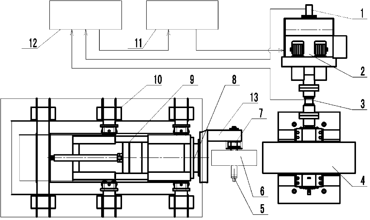
[0046] Such as figure 1As shown, the electric inertia tire braking test bench is characterized in that it includes at least a speed sensor 1, a drive motor 2, a torque sensor 3, a drum device 4, a tire speed sensor 5, a test tire and a brake 6, a mechanical friction brake Dynamic torque measuring device 7, force sensor 8, movable frame 9, fixed frame 10, electric transmission control unit 11 and electric inertia simulation control unit 12; torque sensor 3 is installed between the drive motor 2 and the drum device 4 It is used to measure the output torque of the motor. A speed sensor 1 is installed on the shaft end to measure the rotational speed of the motor and the drum. A mechanical friction braking torque measuring device 7 is installed between the tested tire and the brake 6 and the machine head 13 to measure the brake. The mechanical friction torque, the load cell 8 is installed between the head 13 movable frame 9 to measure the loading force acting on the tire, the movab...


PUM


Abstract

The invention belongs to mechatronics systems, and relates to electric drive simulation of a mechanical rotation inertial system, in particular to an electric inertia tyre braking bench and an electric inertia control method thereof. Drum rotation speed and motor output torque are synchronously collected, a motor torque output value is calculated according to a mathematic model, and the braking bench operates under the state that an ideal drum is close and system proper drag does not exist. Precise matching of rotational inertia is achieved, control precision can meet the requirement of a high-precision test, and investment and operation cost are saved.

Description

technical field [0001] The invention belongs to an electromechanical integration system, and relates to an electric transmission simulation of a mechanical rotary inertia system, in particular to an electric inertia tire braking test bench and an electric inertia control method thereof. Background technique [0002] In the bench test of tire braking, it is necessary to test the braking performance of the brake under different conditions, the essence of which is that the brake consumes the energy set under specific working conditions. Therefore, the brake test bench should have the function of providing specific energy under different working conditions. [0003] The mechanical simulation of the load is realized through the drum. Since the moment of inertia of the drum is fixed, it is impossible to simulate the load accurately all the time. This problem can be well solved by the simulation of the electrical inertia. [0004] The braking torque of the tire brake is composed o...

Claims


Application Information

Patent Timeline
IPC IPC(8): G01L5/28G01M17/02
Inventor 李卫东
Owner CHINA NAT HEAVY MACHINERY RES INSTCO
Why Eureka
Try Eureka