Scanning device for near-field test of antennas

A scanning device and near-field technology, applied in the direction of electromagnetic field characteristics, can solve the problems of low integration, large use limitations, and bulky volume, and achieve the effects of convenient use and maintenance, high automation, and high integration

Active Publication Date: 2013-10-09
成都雷电微力科技股份有限公司
View PDF12 Cites 22 Cited by
  • Summary
  • Abstract
  • Description
  • Claims
  • Application Information

AI Technical Summary

Problems solved by technology

However, most of them adopt a tower-based structure, which is bulky, not highly integrated, and has a complex structure. It is not convenient to attach absorbing materials to reduce the impact of test platform scattering...

Method used


Image

  • Scanning device for near-field test of antennas
  • Scanning device for near-field test of antennas
  • Scanning device for near-field test of antennas

Examples


Embodiment 1

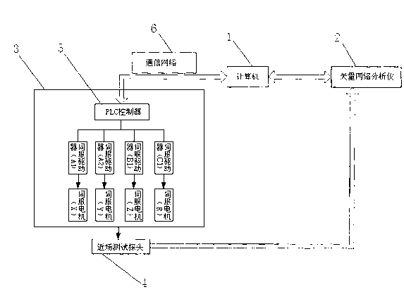
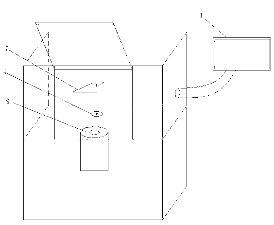
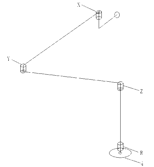
[0018] as attached figure 1 , attached figure 2 , attached image 3 As shown, the scanning device used for antenna near-field testing in this embodiment includes a microwave shielding anechoic chamber with absorbing materials on the wall, and also includes a computer 1, a vector network analyzer 2, a three-dimensional mobile system 3, and a near-field testing probe 4. The computer 1 is connected to the vector network analyzer 2, the input end of the vector network analyzer 2 is connected to the near-field test probe 4, and the near-field test probe 4 is fixed on the front end of the multi-joint mechanical arm 7 of the three-dimensional mobile system 3 , the three-dimensional mobile system 3 includes a PLC controller 5 and four servo drivers (servo driver A1, servo driver A2, servo driver B1, and servo driver C1) in addition to the multi-joint manipulator 7, installed on the multi-joint manipulator 7, the first joint servo motor (X), the second joint servo motor (Y), a probe...


PUM


Abstract

The invention relates to the technical field of microwave tests and in particular relates to a scanning device for near-field test of antennas. The scanning device for near-field test of antennas comprises a microwave shielding darkroom with a wave-absorbing material on the wall and further comprises a computer, a vector network analyzer, a three-dimensional moving system and a near-field test probe, wherein the computer is connected to the vector network analyzer; the input end of the vector network analyzer is connected to the near-field test probe; the near-field test probe is fixed at the front end of a multi-joint robotic arm of the three-dimensional moving system. The three-dimensional moving system comprises a PLC (Programmable Logic Controller), a servo driver, a multi-joint robotic arm and a servo motor. The repeated positioning precise of the probe can reach +/-0.01mm; the positioning planeness can reach +/-0.03mm; connection communication is realized between the PLC controller and the computer by virtue of an Ethernet communication network; the three-dimensional moving system performs real-time precise control by virtue of the computer. The scanning device for near-field test of antennas is high in degree of automation, high in precision, integral in parts and high in integration level and is convenient to use and maintain.

Description

technical field [0001] The invention relates to the technical field of microwave testing, in particular to a scanning device for antenna near-field testing. Background technique [0002] Antenna near-field testing is carried out in a microwave anechoic chamber, which has high precision, high efficiency, and low cost, and is more and more widely used in antenna testing. The scanning device used by the antenna for near-field testing mainly includes the antenna under test and probe system, the antenna under test and probe positioning system, and the test data acquisition and processing system. Among them, the positioning system of the antenna to be tested and the probe is the key platform for antenna near-field testing, and its positioning method and accuracy determine the accuracy of the antenna test results. The main technical index of the antenna and probe positioning system to be tested is its positioning accuracy: the positioning flatness of the probe, the repeat position...

Claims


Application Information

Patent Timeline
IPC IPC(8): G01R29/08
Inventor 廖洁管玉静李灿
Owner 成都雷电微力科技股份有限公司
Why Eureka
Try Eureka