Eureka AIR delivers breakthrough ideas for toughest innovation challenges, trusted by R&D personnel around the world.

Low-pressure and high-power stator preformed winding welding method

A technology for forming windings and welding methods, which is applied to prefabricated windings embedded in motors, shapes/styles/structures of winding conductors, electric components, etc., can solve the problems of not easy to clean up welding waste, unfavorable operator health, and large joint space, etc. Achieve the effect of improving the labor environment and strength, overcoming the cumbersome preparation work, and expanding the welding operation space

Active Publication Date: 2013-10-09
上海马拉松·革新电气有限公司
View PDF7 Cites 4 Cited by
  • Summary
  • Abstract
  • Description
  • Claims
  • Application Information

AI Technical Summary

Problems solved by technology

[0004] The traditional welding method has the following defects: due to the small space for the operator to weld, it is difficult to weld the joint, it takes a long time, the labor intensity is high, and false welding is easy to occur, and the welding quality cannot be guaranteed; it is not easy to clean the debris in the machine base after welding Welding garbage; when welding, asbestos for fire prevention should be placed in the stator (it is cumbersome and not conducive to the health of the operator)
[0008] The cold pressing method has the following defects: Since the connecting sleeve must also be made of copper, and in order to achieve a better cold pressing effect, it is necessary to design a test cold pressing die for different cross-sectional areas of the number of coils, and there are long preparation times and copper consumption. It has disadvantages such as large size and large space for joints inside the stator, but it also has the advantage of not needing to clean the inside of the machine base after the joints are completed

Method used


Image

  • Low-pressure and high-power stator preformed winding welding method
  • Low-pressure and high-power stator preformed winding welding method
  • Low-pressure and high-power stator preformed winding welding method

Examples


Embodiment Construction

[0037] The specific implementation manners of the present invention will be described in detail below in conjunction with the accompanying drawings of the embodiments.

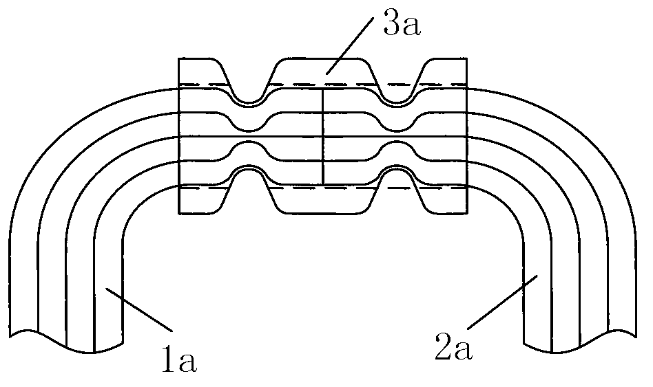
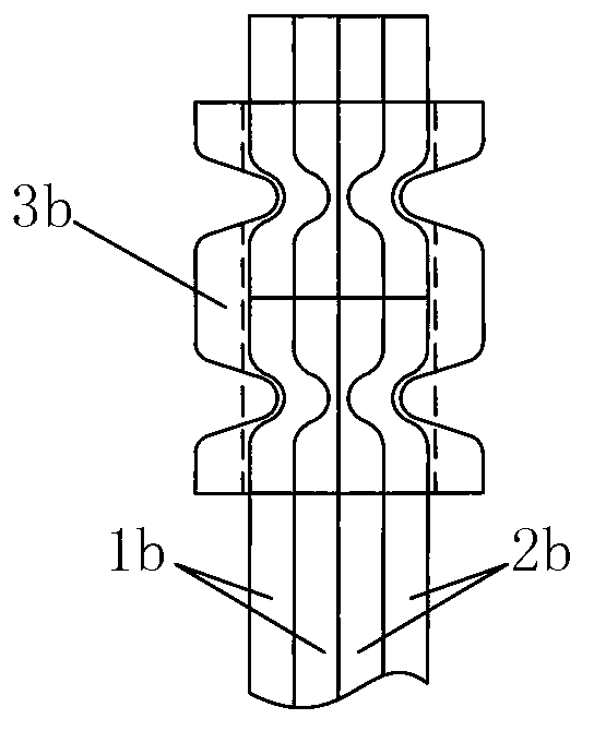
[0038] S1, arranging multiple copper rods on the winding machine to wind a single coil ring: After arranging multiple copper rods in order, wind them on the winding machine with a winding mold to form a coil ring such as figure 2 Oval single coil loop shown;

[0039] S2, pull the single coil ring on the drawing machine to form a single-turn forming coil: use the forming die to pull the above-mentioned single coil ring on the drawing machine into such figure 2 For the single-turn forming coil shown, the two ends of the single-turn forming coil are provided with nose rings 31 respectively;

[0040] S3, forming a formed coil group: stack several single-turn formed coils completed according to the steps of S1-S2 to form a formed coil group, and the number of single-turn formed coils contained in a formed coil g...


PUM


Abstract

The invention discloses a low-pressure and high-power stator preformed winding welding method and relates to the manufacturing method of generator stators. The low-pressure and high-power stator preformed winding welding method solves the problems that existing junction welding is difficult, long in preparation time and large in quantity of copper used. The method comprises the steps of coiling a plurality of copper bars into single coil rings, pulling the single coiling rings to form single-turn formed coils, manufacturing a formed coil set with the single-turn formed coils, embedding the formed coil set in a stator machine base, manufacturing a cut formed coil set, manufacturing a connected formed coil set, taking the connected formed coil set out of the stator machine base for welding to form a linkage of formed coil, manufacturing single-linkage insulating formed coils, embedding an integral coil formed by the single-linkage coils in an enclosing mode in the stator machine base to form a stator winding, and splicing the single-linkage insulating formed coils to achieve stator preformed winding welding. According to the low-pressure and high-power stator preformed winding welding method, early-stage preparation work is simple, machining is convenient, labor intensity is low, copper consumption is low, splicing is firm, and the stator machine base does not need to be cleaned.

Description

technical field [0001] The invention relates to a method for manufacturing a generator stator, in particular to a low-voltage high-power stator forming winding welding method. Background technique [0002] At present, the stator windings of low-voltage and high-power three-phase AC generators at home and abroad basically use formed windings. There are generally two types of joints for such windings: [0003] 1. Embed the formed coil into the iron core first, and then connect it inside the machine base. The joint adopts the traditional welding method. [0004] The traditional welding method has the following defects: due to the small space for the operator to weld, it is difficult to weld the joint, it takes a long time, the labor intensity is high, and false welding is easy to occur, and the welding quality cannot be guaranteed; it is not easy to clean the debris in the machine base after welding Welding garbage; when welding, asbestos for fire prevention should be placed i...

Claims


Application Information

Patent Timeline
IPC IPC(8): H02K15/04H02K15/06H02K3/04
Inventor 徐文洁陆永键王国良
Owner 上海马拉松·革新电气有限公司
Why Eureka
Eureka Blog
Learn More