Vehicle bumper structure
A technology for bumpers and vehicles, applied in bumpers, vehicle parts, vehicle safety arrangements, etc., can solve problems such as waste of design space and complex interval management.
- Summary
- Abstract
- Description
- Claims
- Application Information
AI Technical Summary
Problems solved by technology
Method used
Image

Examples
Embodiment Construction
[0035] Hereinafter, the present invention will be described in detail based on the illustrated embodiments.
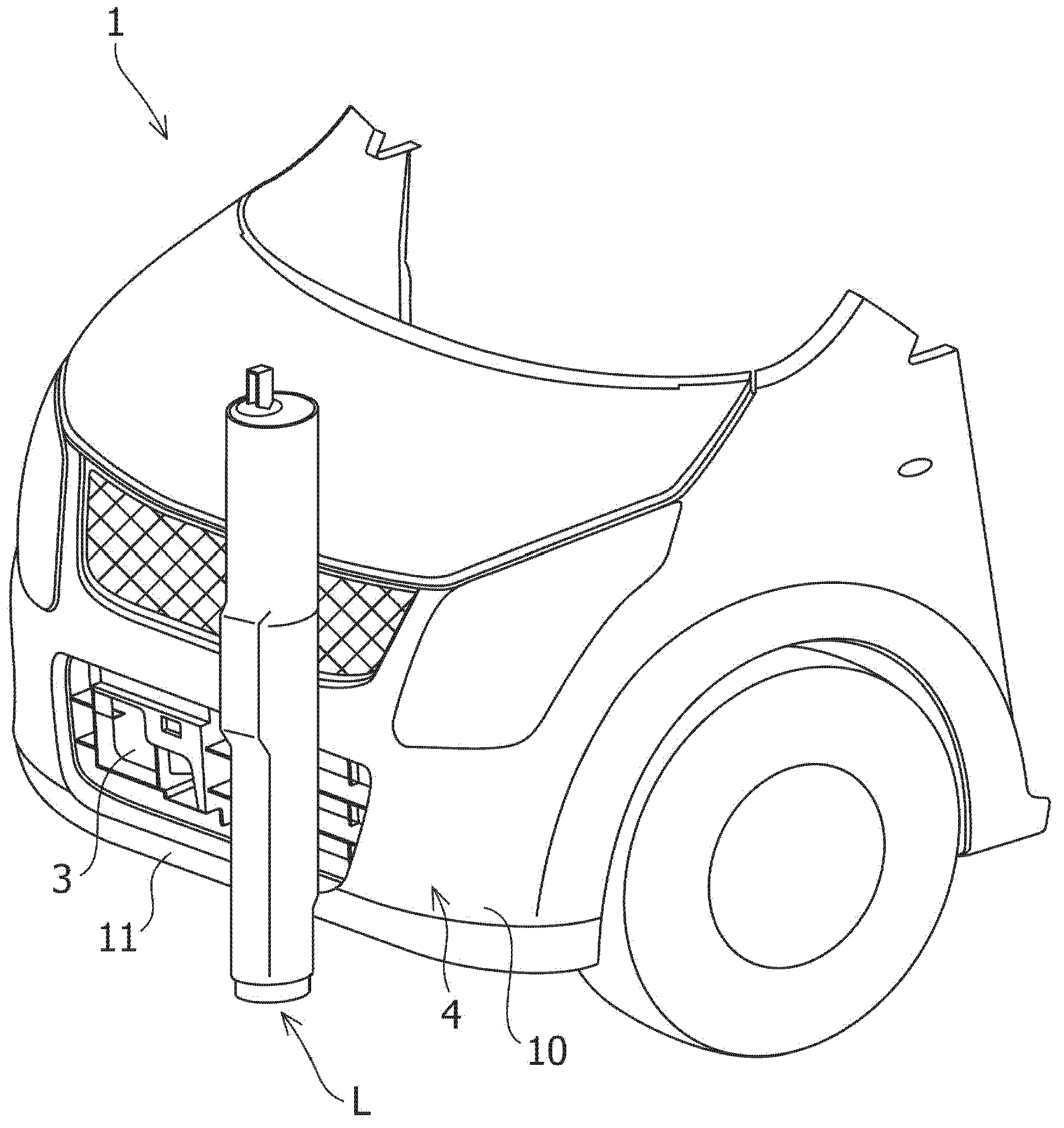
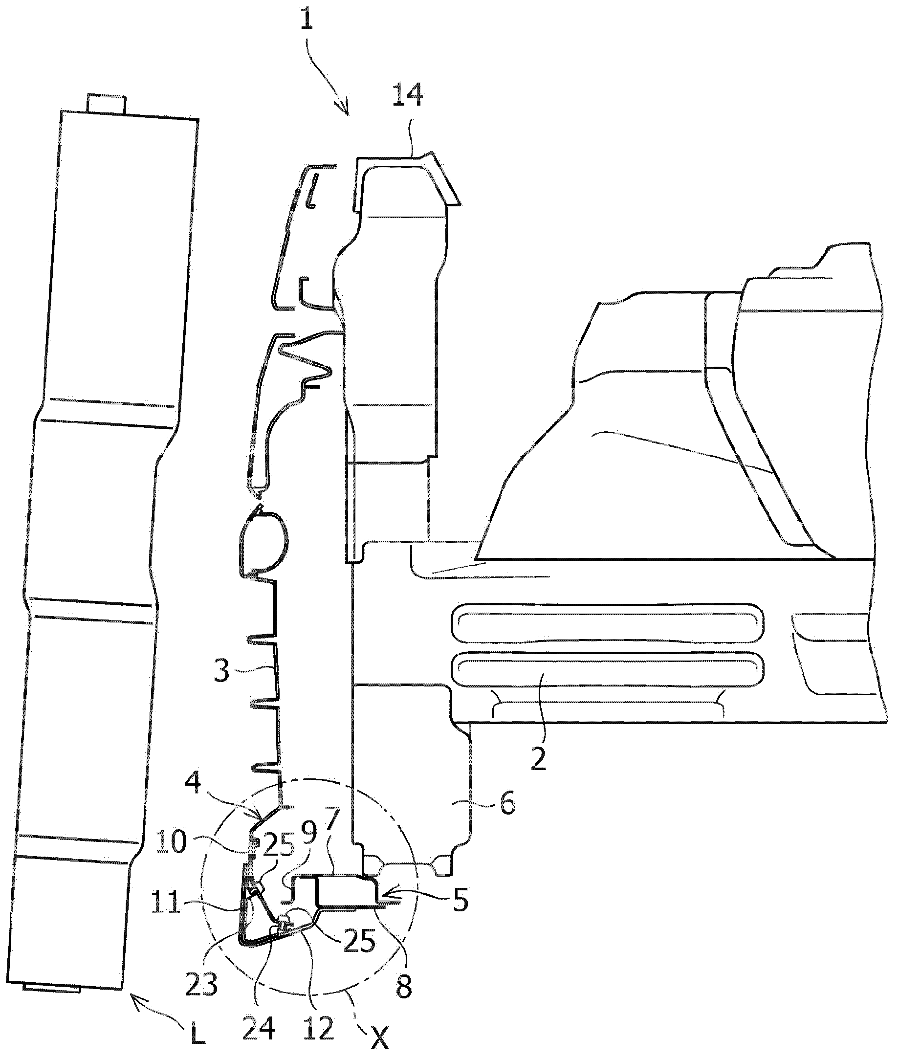
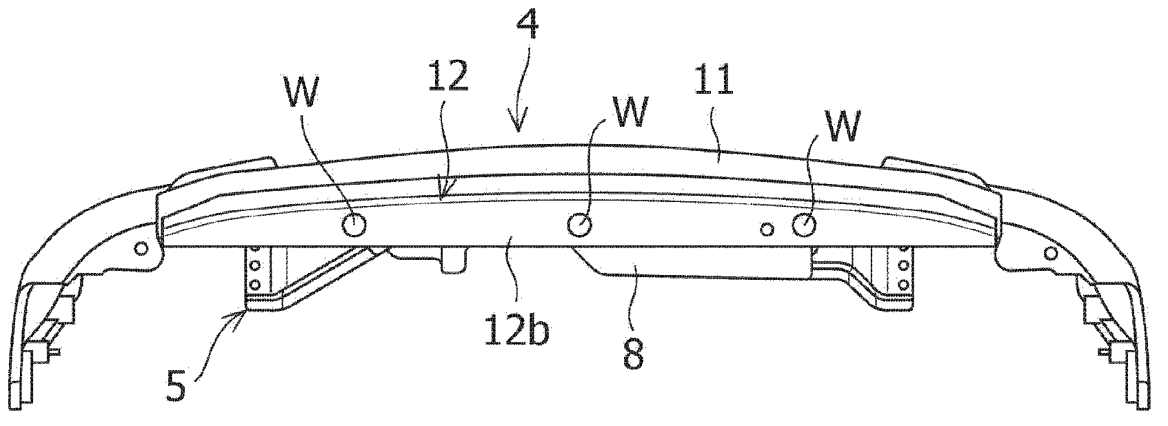
[0036] Figure 1 to Figure 5 A bumper structure of a vehicle according to an embodiment of the present invention is shown.
[0037] Such as figure 1 and figure 2 As shown, the vehicle front 1 to which the bumper structure according to the embodiment of the present invention is applied mainly includes: a pair of left and right apron side members (apron side members) 2 extending along the front-rear direction of the vehicle with an intervening The left and right sides in the vehicle width direction are arranged with gaps; and the resin bumper grille 3 and the front bumper 4 located in front of the vehicle of these skirt side members 2, the bumper grille 3 is arranged on the back side of the front bumper 4 .
[0038] In the vehicle front portion 1 of the present embodiment, the pedestrian's leg L extending in the vehicle up-down direction is located on the vehicle l...
PUM
 Abstract
Description
Claims
Application Information