Liquid suction device
A suction device and liquid technology, applied in the direction of valve device, gas/liquid distribution and storage, ship hull, etc., can solve problems such as inability to operate continuously, and achieve the effect of high-efficiency unloading operations
- Summary
- Abstract
- Description
- Claims
- Application Information
AI Technical Summary
Problems solved by technology
Method used
Image
Examples
no. 1 example
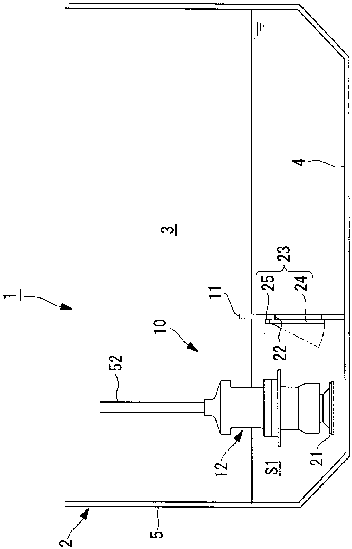
[0071] As follows, while referring to figure 1 A liquid inhalation device according to a first embodiment of the present invention will be described.
[0072] figure 1 It is a cross-sectional view of a liquefied natural gas carrier (hereinafter referred to as "LNG ship") 1 in which the liquid suction device 10 of this embodiment is disposed in a membrane-type liquid tank 3 .
[0073] The LNG carrier 1 is a ship for transporting LNG, and a plurality of liquid tanks (in this embodiment, membrane type liquid tanks) 3 filled with LNG are provided in the hull 2 .
[0074] A plurality of tanks 3 in the length direction of the hull 2 (with figure 1 The vertical direction of the drawing) are arranged side by side. Each liquid tank 3 is a low-temperature heat-insulating container filled with cryogenic LNG inside, has a shape conforming to the space of a square tank, and has a bottom surface (flat surface) 4 having a predetermined area at the bottom.
[0075] A liquid suction de...
no. 2 example
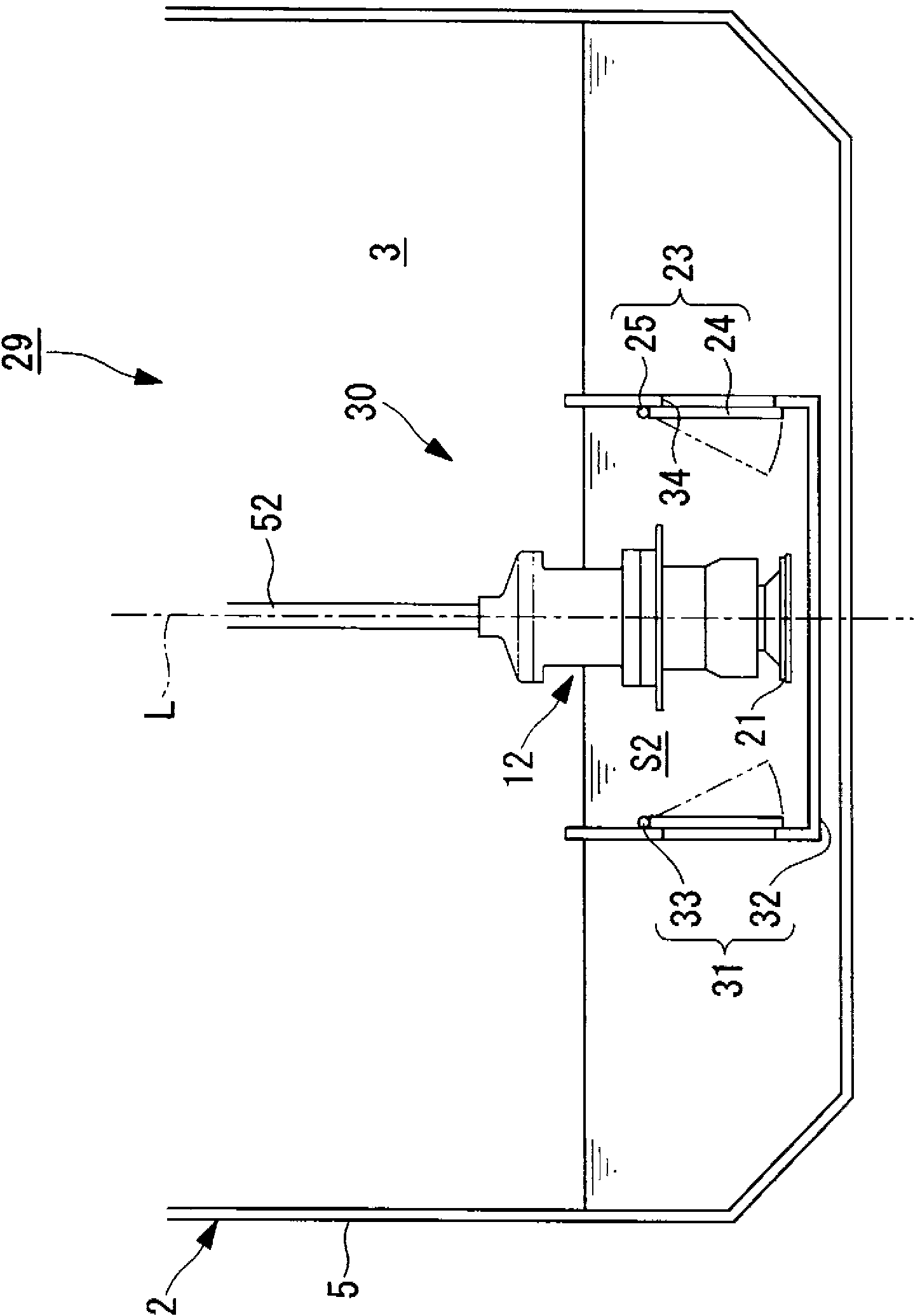
[0084] while referring to figure 2 A liquid inhalation device according to a second embodiment of the present invention will be described.
[0085] figure 2 It is a cross-sectional view of an LNG carrier 29 in which the liquid suction device 30 of this embodiment is arranged in the membrane tank 3 .
[0086] The liquid suction device 30 of this embodiment is arranged on the center line L of the hull 2, and differs from the above-mentioned first embodiment in that a container 31 is provided instead of the bulkhead 11. Since other structural elements are the same as those of the first embodiment described above, descriptions of these structural elements are omitted here.
[0087] Components that are the same as those in the first embodiment described above are assigned the same symbols.
[0088] The liquid intake device 30 has a container 31 and a (cargo) pump 12 .
[0089] The container 31 prevents the suction part 21 of the pump 12 provided at the lowermost part of the p...
no. 3 example
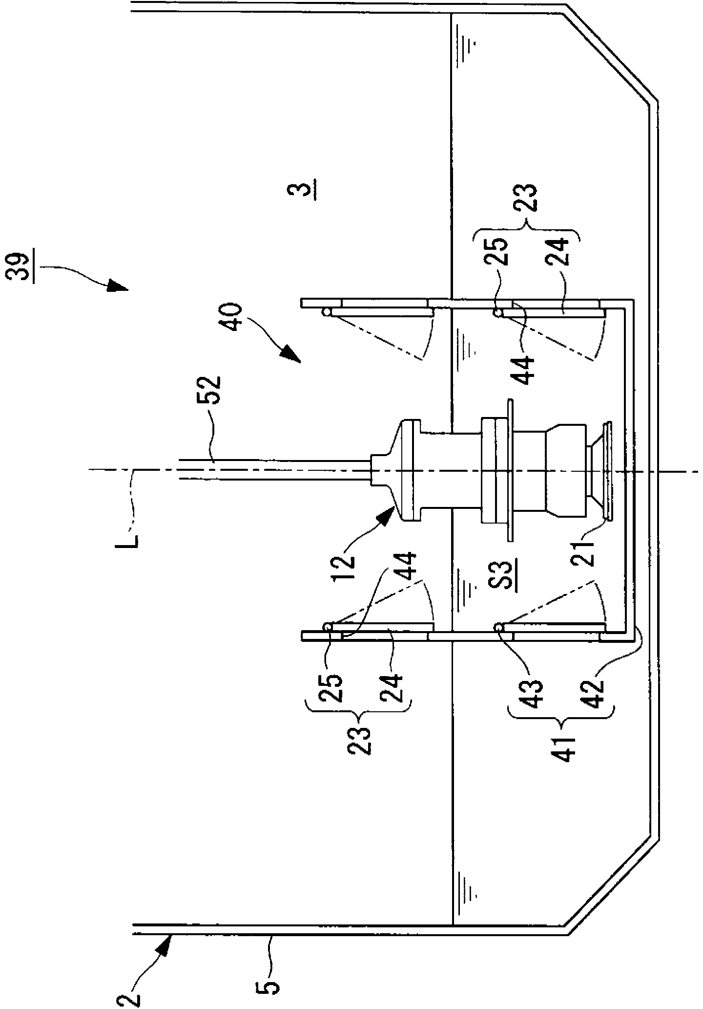
[0094] while referring to image 3 A liquid suction device according to a third embodiment of the present invention will be described.
[0095] image 3 It is a cross-sectional view of an LNG carrier 39 in which the liquid suction device 40 of this embodiment is arranged in the membrane tank 3 .
[0096] The liquid inhalation device 40 of this embodiment differs from the second embodiment described above in that a container 41 is provided instead of the container 31 . Since other structural elements are the same as those of the above-mentioned embodiments, descriptions of these structural elements are omitted here.
[0097] Components that are the same as those in the above-mentioned embodiments are assigned the same symbols.
[0098] The liquid intake device 40 has a container 41 and a (cargo) pump 12 .
[0099] The container 41 prevents the suction part 21 of the pump 12 provided at the lowermost part of the pump 12 from being exposed to the liquid surface of the LNG by ...
PUM
 Abstract
Description
Claims
Application Information
 - R&D
- Intellectual Property
- Life Sciences
- Materials
- Tech Scout
- Unparalleled Data Quality
- Higher Quality Content
- 60% Fewer Hallucinations
Browse by: Latest US Patents, China's latest patents, Technical Efficacy Thesaurus, Application Domain, Technology Topic, Popular Technical Reports.
© 2025 PatSnap. All rights reserved.Legal|Privacy policy|Modern Slavery Act Transparency Statement|Sitemap|About US| Contact US: help@patsnap.com


