Heat exchanger and air conditioner
A technology for heat exchangers and heat exchange parts, applied in the fields of heat exchangers and air conditioners, can solve problems such as insufficient performance of condensers
- Summary
- Abstract
- Description
- Claims
- Application Information
AI Technical Summary
Problems solved by technology
Method used
Image
Examples
no. 1 approach
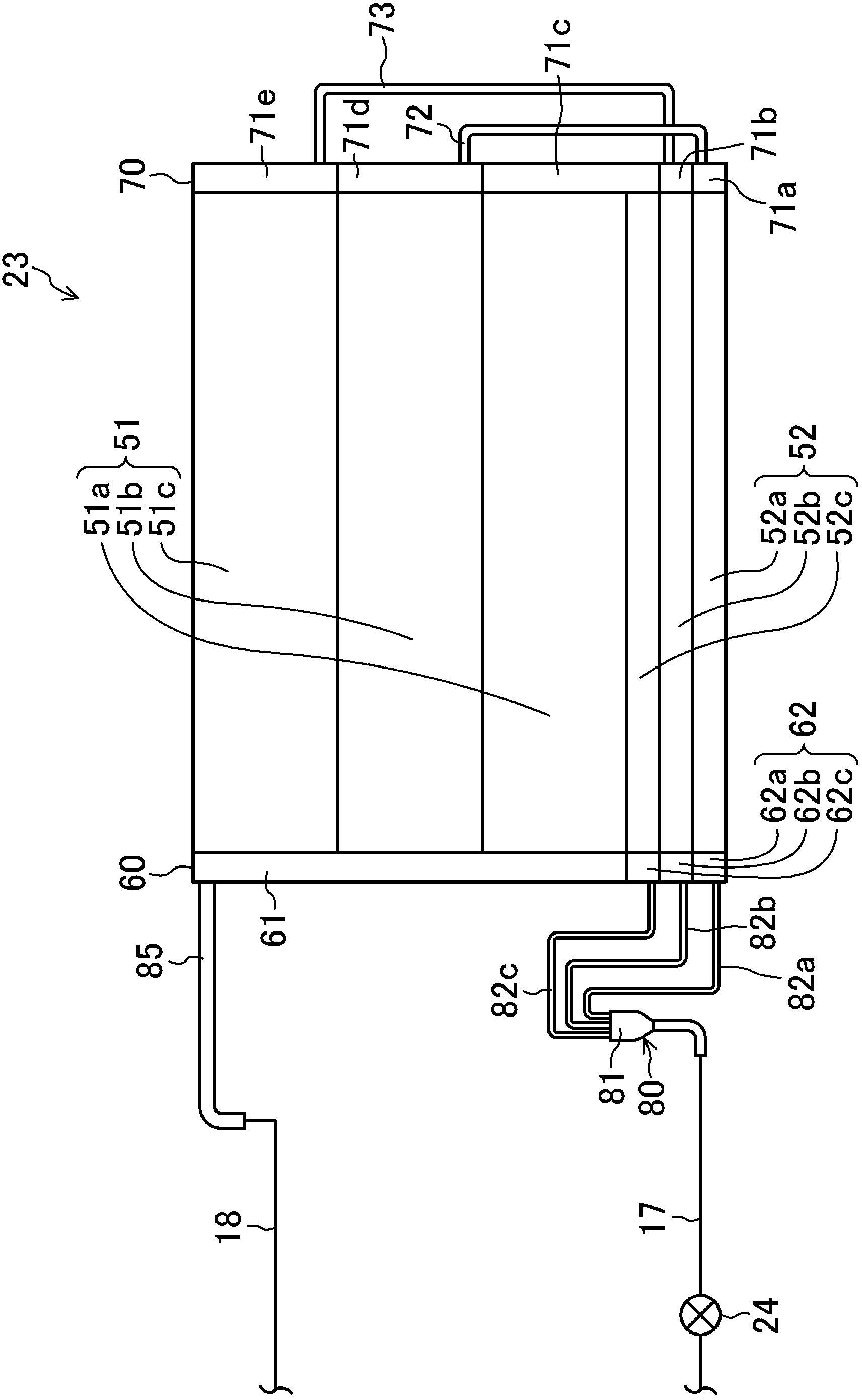
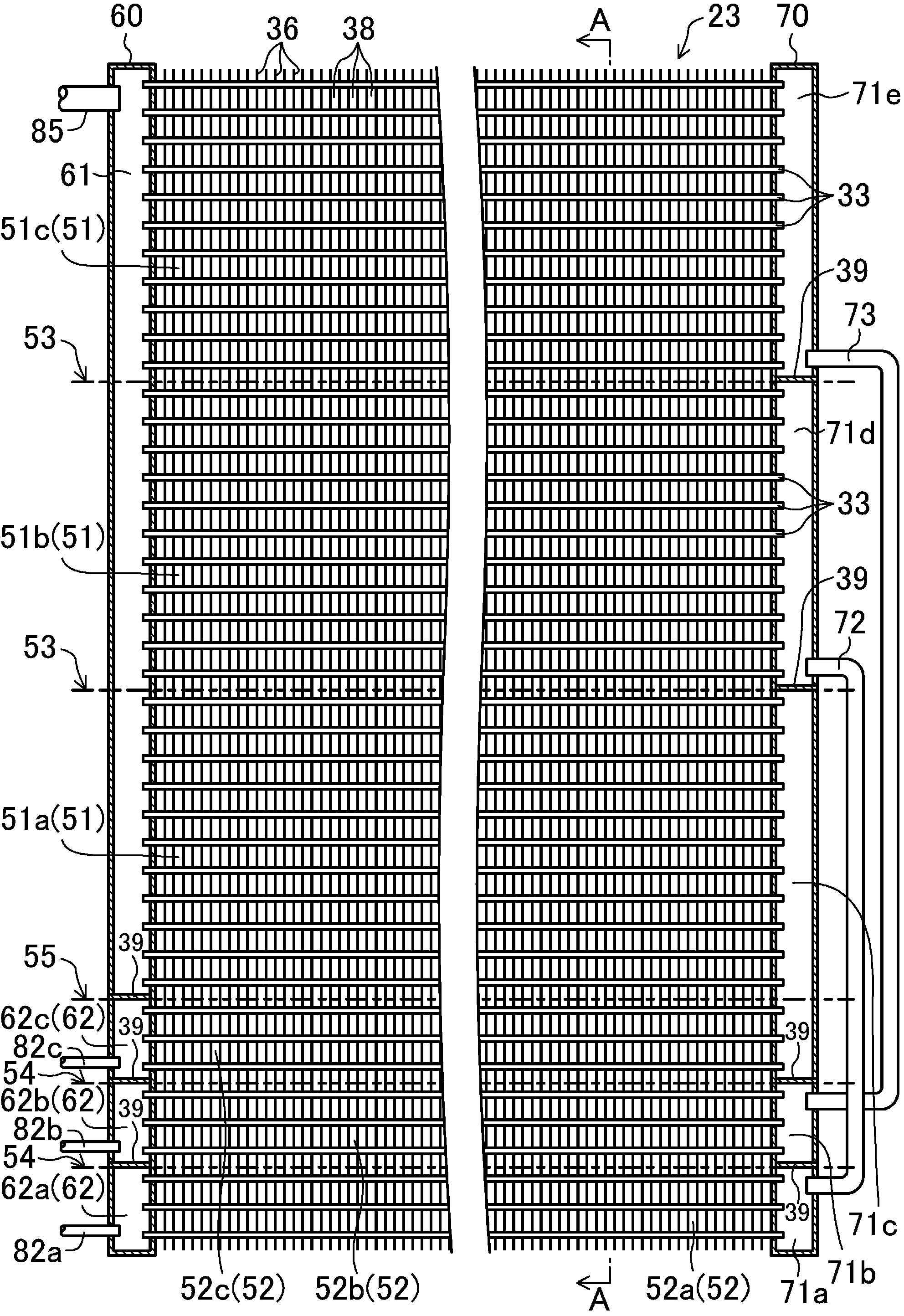
[0055] The first embodiment of the present invention will be described. The heat exchanger in this embodiment is the outdoor heat exchanger 23 provided in the air conditioner 10.
[0056] -Air conditioning equipment-
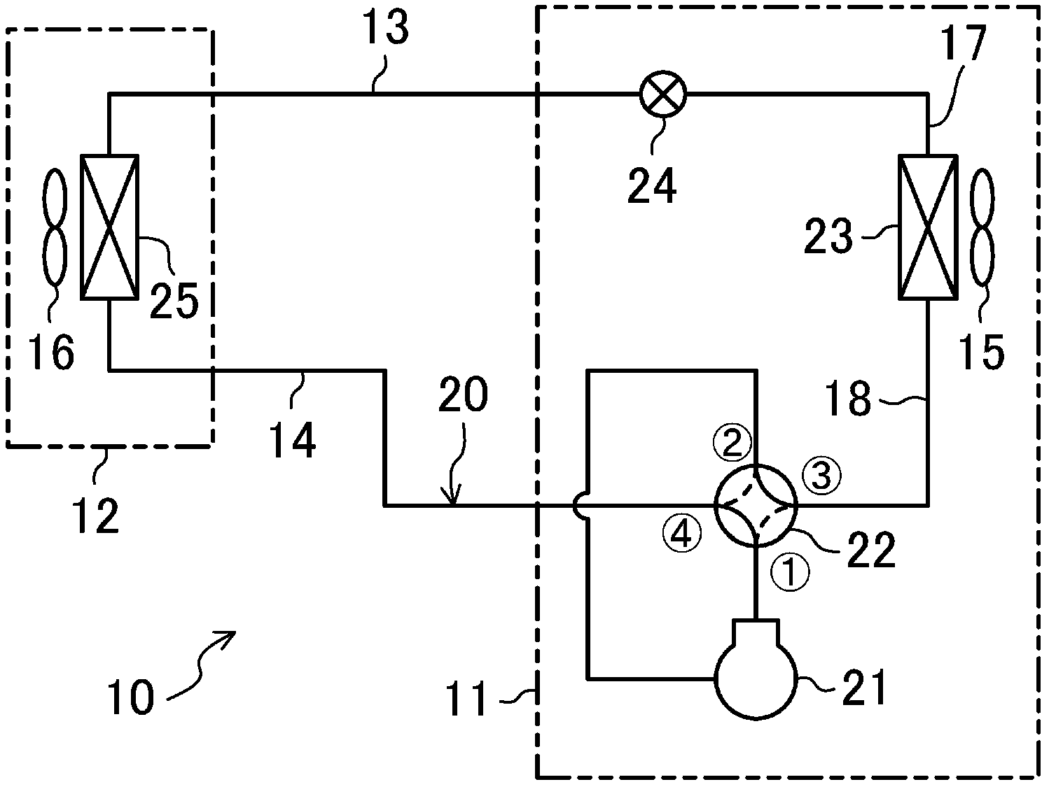
[0057] Reference figure 1 The air conditioner 10 is described.
[0058]
[0059] The air conditioner 10 includes an outdoor unit 11 and an indoor unit 12. The outdoor unit 11 and the indoor unit 12 are connected to each other via a liquid side connection pipe 13 and a gas side connection pipe 14. In the air conditioner 10, the outdoor unit 11, the indoor unit 12, the liquid side connecting pipe 13 and the air side connecting pipe 14 form a refrigerant circuit 20.
[0060] A compressor 21, a four-way switching valve 22, an outdoor heat exchanger 23, an expansion valve 24, and an indoor heat exchanger 25 are provided in the refrigerant circuit 20. The compressor 21, the four-way reversing valve 22, the outdoor heat exchanger 23 and the expansion valve 24 are installed ...
no. 2 approach
[0113] The second embodiment of the present invention will be described. This embodiment is obtained by changing the structure of the outdoor heat exchanger 23 of the first embodiment. Here, refer appropriately Figure 7 versus Figure 8 The difference between the outdoor heat exchanger 23 of this embodiment and the first embodiment described above will be described.
[0114] Such as Figure 7 As shown, the flat tube 33 of the outdoor heat exchanger 23 is divided up and down into an upper heat exchange area 51 and a lower heat exchange area 52 as in the aforementioned first embodiment. The upper heat exchange area 51 is divided into three main heat exchange parts 51a-51c arranged up and down, and the lower heat exchange area 52 is constituted by one auxiliary heat exchange part 52a. That is, in the upper heat exchange area 51, a first main heat exchange portion 51a, a second main heat exchange portion 51b, and a third main heat exchange portion 51c are formed in order from botto...
no. 3 approach
[0135] The third embodiment of the present invention will be described. The present embodiment is obtained by changing the structure of the second manifold 70 of the outdoor heat exchanger 23 of the above-mentioned first embodiment, and the structure other than that is the same as the first embodiment. In this embodiment, appropriately refer to Picture 11 versus Picture 12 , Only the structure of the second manifold 70 of the outdoor heat exchanger 23 will be described.
[0136] Such as Picture 12 As shown, the internal space of the second manifold 70 of the outdoor heat exchanger 23 is divided by two partitions 39 left and right to divide three communication spaces 71a-71c. Specifically, in the internal space of the second manifold 70, press Picture 12 In order from the right side to the left side, a first communication space 71a, a second communication space 71b, and a third communication space 71c are formed. The first communication space 71a communicates with the ends of...
PUM
 Abstract
Description
Claims
Application Information
 - R&D
- Intellectual Property
- Life Sciences
- Materials
- Tech Scout
- Unparalleled Data Quality
- Higher Quality Content
- 60% Fewer Hallucinations
Browse by: Latest US Patents, China's latest patents, Technical Efficacy Thesaurus, Application Domain, Technology Topic, Popular Technical Reports.
© 2025 PatSnap. All rights reserved.Legal|Privacy policy|Modern Slavery Act Transparency Statement|Sitemap|About US| Contact US: help@patsnap.com


