Defrosting cycle control

a cycle control and defrosting technology, applied in the field of defrosting, can solve the problems of undetectable high energy consumption, high energy consumption, and loss of heat from the building to the outside to a higher degree, and achieve the effect of improving energy recovery and more efficient defrosting

Active Publication Date: 2020-07-30
SWEGON AB
View PDF5 Cites 2 Cited by
  • Summary
  • Abstract
  • Description
  • Claims
  • Application Information

AI Technical Summary

Benefits of technology

[0007]The object of the present invention is to provide an improved energy recovery and more efficient defrosting for an Air Handling Unit (AHU) to be used in a ventilation system in a building.
[0015]The kind of system described above is in particular useful in cold climates where a lot of heat may be regained by heat exchanging warm extract air from inside the building with cold supply air from the outside. In order to be able to recover as much heat as possible, it is desired to cool down the extract air exhausted as much as possible. There may thus be a risk for ice growth on the heat recovery system as a result of the cooling down of the extract air, which often is rather humid, in the heat exchanger when the temperature is below zero degrees Celsius. In the case of a heat pump used, there is a frost risk also when the temperature is above zero degrees Celsius. Ice on the heat exchanger or heat pump will decrease the heat exchange efficiency in the heat exchanger or heat pump, thus reducing the heat recovery, and also increase the pressure drop over the heat exchanger such that there is needed an increased force, and thus increased energy consumption, in order to provide a desired air flow through the heat exchanger.
[0016]A beneficial configuration of the AHU is that the first media phase change unit is located in the supply air channel downstream of the heat exchanger and said second media phase change unit is located in the extract air channel downstream of the heat exchanger. This means that when the AHU is set to work in heat recovery mode will the air flows in the respective channels, i.e. the supply air channel and extract air channels, first be heat exchanged and thereafter will the remaining heat in the extract air be used to further heat the supply air leaving the heat exchanger. The heat exchanger, e.g. a rotating heat exchanger wheel, is well adapted to efficiently recover heat when the temperature differences in the air flows are significant but may not work well when there are small temperature differences meanwhile a heat pump may regain heat also when the heat differences are small or even negative.
[0030]The ECU could be connected to the pressure indicating means or pressure sensors in order to receive input signals from these sensors. The ECU is preferably also connected to flow controllers, e.g. the supply air damper and the extract air damper, in order to send control signals to these flow controllers. The ECU may also be programmed to output a defrost cycle initiation signal when there is an indication of an undesired high level of ice in the heat exchanger or heat pump system, e.g. from sensing an increased pressure drop somewhere in the AHU being above a defined limit. The ECU may be programmed to switch the function of the AHU from a normal heat recovery mode to a defrost mode and start a defrost cycle when the pressure indicating system estimates a pressure drop over the second media phase change unit above a first predefined limit. In case a pressure drop limit is used by the ECU for initiating a defrost cycle is it suitable to program the ECU to switch off the defrost mode and end the defrost cycle when the pressure indicating system estimate a pressure drop below a second predefined limit. Using a heat pump arrangement, the ECU may be programmed to set said media phase change unit in the supply air channel to function as an condenser in order to release heat to the fresh intake air and the media phase change unit in the extract air channel to function as an evaporator absorbing heat from the exhaust air channel when the AHU is working in its normal heat recovery mode. When a defrost operation is desired could the ECU be programmed to set said the media phase change unit in the supply air channel to function as an evaporator in order to absorb heat from its surroundings and the media phase change unit in the extract air to function as a condenser in order to release heat to its surroundings when the AHU is working in its defrost mode. Hence, a reversible heat pump may be useful both for heat recovery and defrost operation. The defrost cycle initiation signal thus implies a possibility for various control signals to be sent from the ECU. The ECU could for example be programmed to send a control signal to flow controllers, e.g. one or several dampers, and change the flow channel configuration from admitting a large supply air flow when the AHU is in the heat recovery mode to reduce or restrict the supply air intake after a defrost initiation signal setting the AHU to be in a defrost mode. The defrost initiation signal preferably also changes the settings or positions of other dampers and other flow controllers. By restricting the flow of supply air by the supply air damper will cooling effect be reduced and accumulated ice start to defrost by the warm flow of exhaust air from the building in the extract air and supply air channels. In addition, fans and possible by-pass dampers or recirculation dampers may be controlled.
[0043]In general, the time period for the defrost cycle corresponds to the amount of ice formation on the device to be defrosted. In case there is need of a too long defrost cycle, it could indicate the formation of ice is so quick that the heat recovery on the AHU not is able to recover heat efficiently due to the ice formation. If the criteria for initiating the defrost cycle is changed such that the defrost cycle is shorter will it most certainly also imply a shorter heat recovery cycle thus reducing the time during ice formation will occur and thus stop the heat recovery cycle before too much ice is built up and the efficiency of the heat recovery mode is seriously affected. On the contrary, if the time for the defrost cycle is too short is it possible that the defrost cycle is starting before the ice formation contributes with any significant negative impact on the heat recovery thus causing the defrost cycle to start too early to be efficient for the overall energy efficiency. Hence, by changing the criteria for initiating and / or terminating the defrost cycle such that it will longer will most certainly allow more ice formation, but still without any serious impact on the heat transfer function, and also allow the AHU to be in its energy efficient heat recovery mode for a longer time.
[0047]the first, higher pressure drop limit is decreased and / or the second, lower pressure drop limit is increased when the defrost cycle is longer than a second predefined time period. For example, the threshold for starting the defrost cycle will be decreased and thus less ice will be allowed to form before the defrost cycle is started. This means that the defrost cycle may start before it is needed to perform a defrost operation for an efficient operation of the AHU there will be an excessive amount of defrost cycles performed over time thus decreasing the energy efficiency of the AHU.

Problems solved by technology

However, there is always a loss in the energy efficiency during such a defrost cycle since the heat exchanger cannot be fully used for its normal purpose, that is to say heat recovery, which results in an undesirably high energy consumption.
Hence, heat from the building to the outside will be lost to a higher degree during the defrost operation.

Method used


Image

  • Defrosting cycle control

Examples


Embodiment Construction

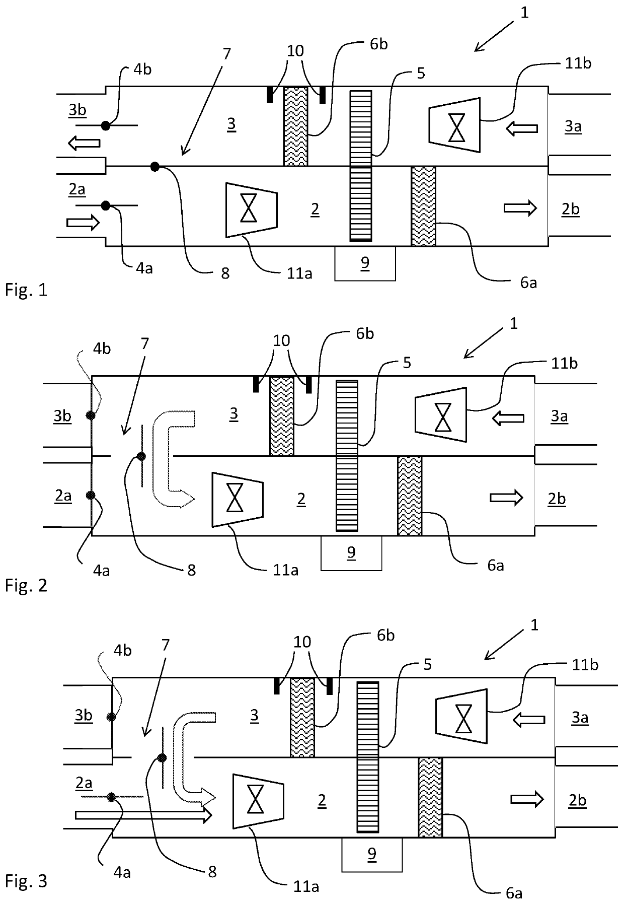
[0052]In FIGS. 1-3 is disclosed an Air Handling Unit (AHU) 1 according to an embodiment of the invention. The AHU 1 comprises a supply air channel 2 having a supply air inlet 2a and a supply air outlet 2b for delivering fresh air to an air ventilation system in a building. The AHU further comprises an extract air channel 3 having an extract air inlet 3a receiving extract air, also commonly called exhaust air or indoor air, and guiding the extract air to the outside through an extract air outlet 3b. Hence, the left side of the AHU in the figures is intended to be connected to the surroundings or outdoor while the right side of the figures is intended to be connected to an air ventilation system in a building for distribution of fresh air to the building and extraction of exhaust air from the interior of the building. In order to control the air flow in the supply air channel 2 is the AHU 1 provided with a supply air damper 4b in the supply air channel 2 close to the supply air outlet...


PUM


Abstract

An Air Handling Unit for a ventilation system in a building has supply and extract air channels, each with an inlet and an outlet for guiding air to and from a building. Each air channel includes a damper controlling air flow. The air channels are in a heat exchanging relation to each other. The AHU also includes a fan and an Electronic Control Unit. The ECU outputs a defrost cycle initiation signal to defrost the heat recovery arrangement. The ECU outputs a defrost cycle termination signal to end the defrost cycle upon indication of the defrosting being completed. To optimize the defrost cycle time the ECU changes the first or second criterion for defrost cycle termination signal depending on the time for performing the defrost cycle such that the time period of the defrost cycle is prolonged / shortened when the defrost cycle time period is shorter / longer than preferred.

Description

TECHNICAL FIELD[0001]The present invention relates to an Air Handling Unit (AHU) for providing fresh air to a building. The invention is in particular directed to the feature of defrosting, or deicing, a heat recovery arrangement exchanging heat between the extract air flow and supply air flow in the AHU. The invention also relates to method for defrosting of an AHU.BACKGROUND[0002]In offices and other larger premises, there is often a need to be able to control the indoor climate separately in different parts of the premises or in individual rooms. An accurate local temperature and ventilation control is required to ensure a sufficient comfort level for the persons present in a building. Also heat generated by electric appliances and heat and exhaled air generated by persons inside the building have to be taken into account for the control. Together with the prevailing weather conditions, these factors have a large influence on the instantaneous demand for heating, cooling and vent...

Claims


Application Information

Patent Timeline
Patent Type & Authority Applications(United States)
IPC IPC(8): F24F11/41F24F12/00
CPCF24F12/003F24F11/41F24F12/006F24F11/65F24F11/61Y02B30/52Y02B30/56F24F11/74
Inventor GUSTAVSSON, ANDREASOLTEGEN, DANIELJOHANSSON, DANIELFRANSSON, ANDERSAHL, MAGNUS
Owner SWEGON AB
Why Eureka
Try Eureka