
Double pipe

Active Publication Date: 2019-04-11
MARELLI CABIN COMFORT JAPAN CORPORATION
View PDF33 Cites 3 Cited by
  • Summary
  • Abstract
  • Description
  • Claims
  • Application Information

AI Technical Summary

Benefits of technology

The present invention provides a double pipe that prevents the inner pipe from being crushed due to pressure differences and improves heat exchange efficiency between a gaseous cooling medium and a liquid cooling medium. This is achieved by using a helical plate member that partitions the interior of the inner pipe into multiple chambers and increases rigidity over the whole radial directions, preventing the inner pipe from being crushed and improving heat exchange efficiency.

Problems solved by technology

In addition, with the double pipe disclosed in JP4350079B2, although protrusions and recesses are formed helically on a surface of the inner pipe, they do not form a structure for supporting the structure of the inner pipe itself.
As a result, a rigidity needs to be secured by increasing a thickness of the inner pipe, and it is difficult to increase the heat exchange efficiency between the gaseous cooling medium and the liquid cooling medium.

Method used


Image

  • Double pipe
  • Double pipe
  • Double pipe

Examples


Embodiment Construction

[0016]An embodiment of the present invention will be described below with reference to the drawings.

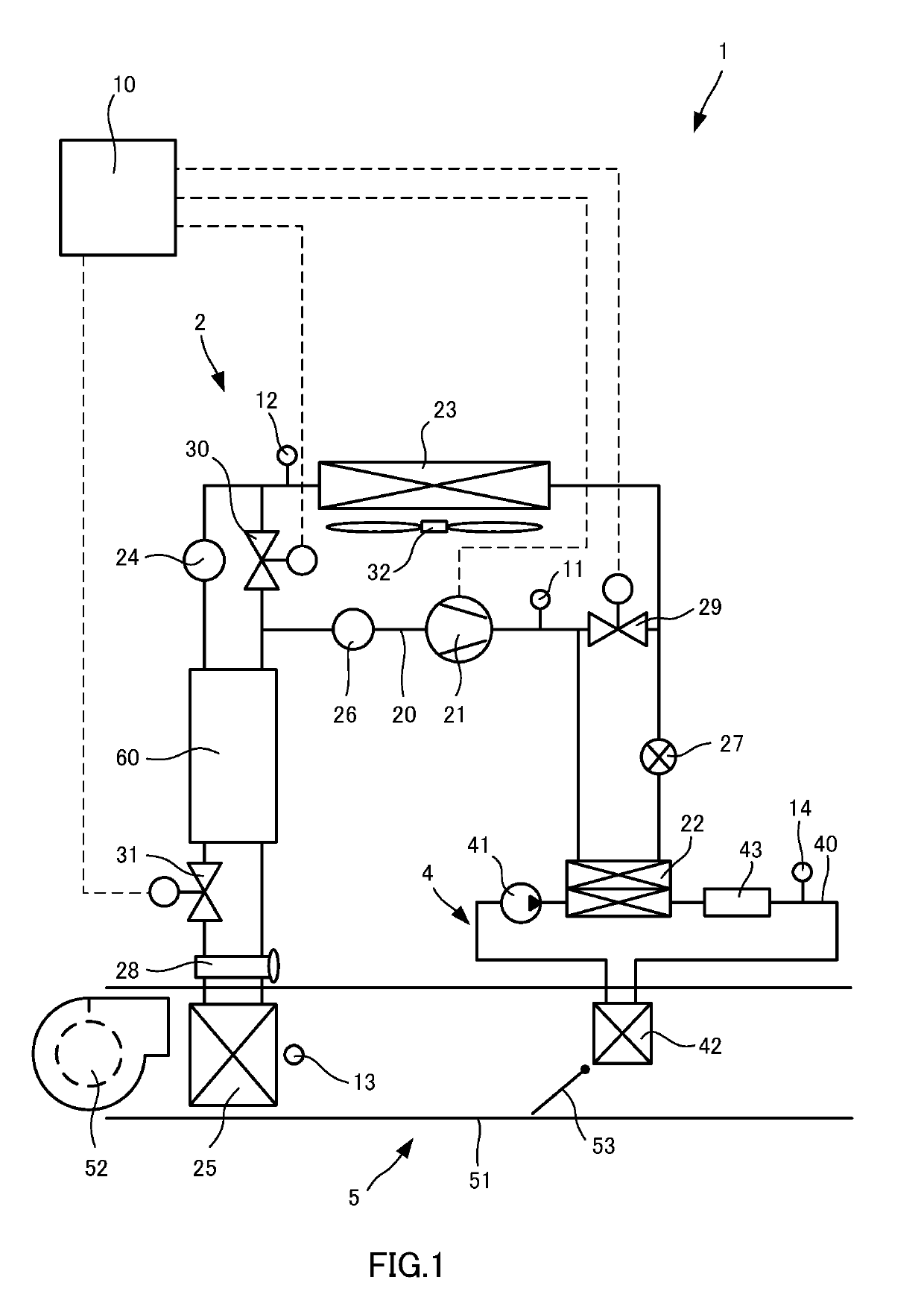
[0017]FIG. 1 is a schematic configuration diagram showing an air-conditioning device 1 to which a double pipe 61 according to the embodiment of the present invention is applied.

[0018]The air-conditioning device 1 is a heat pump system capable of performing a cabin cooling operation and a cabin heating operation including a refrigeration cycle 2 through which cooling medium circulates, a high-water temperature cycle 4 through which hot water circulates, an HVAC (Heating Ventilation and Air Conditioning) unit 5 through which air used for air-conditioning in a vehicle cabin passes, and a controller 10 that controls operation of valves, etc. For example, HFC-134a is used as the cooling medium, and an antifreeze is used as the hot water.

[0019]The refrigeration cycle 2 includes a compressor 21, a fluid-cooled condenser 22, an external heat exchanger 23, a liquid tank 24, an internal heat ex...


PUM


Abstract

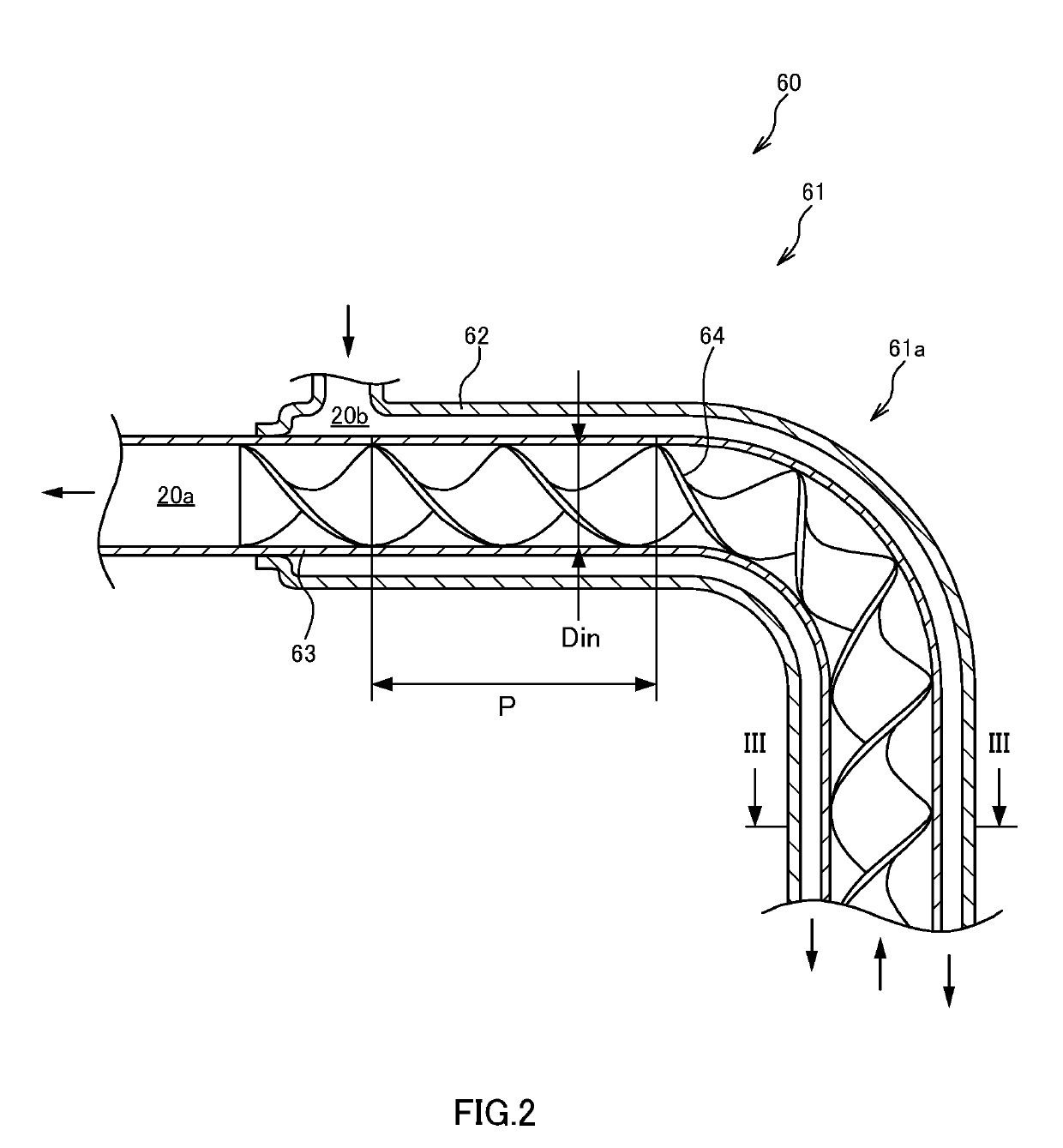
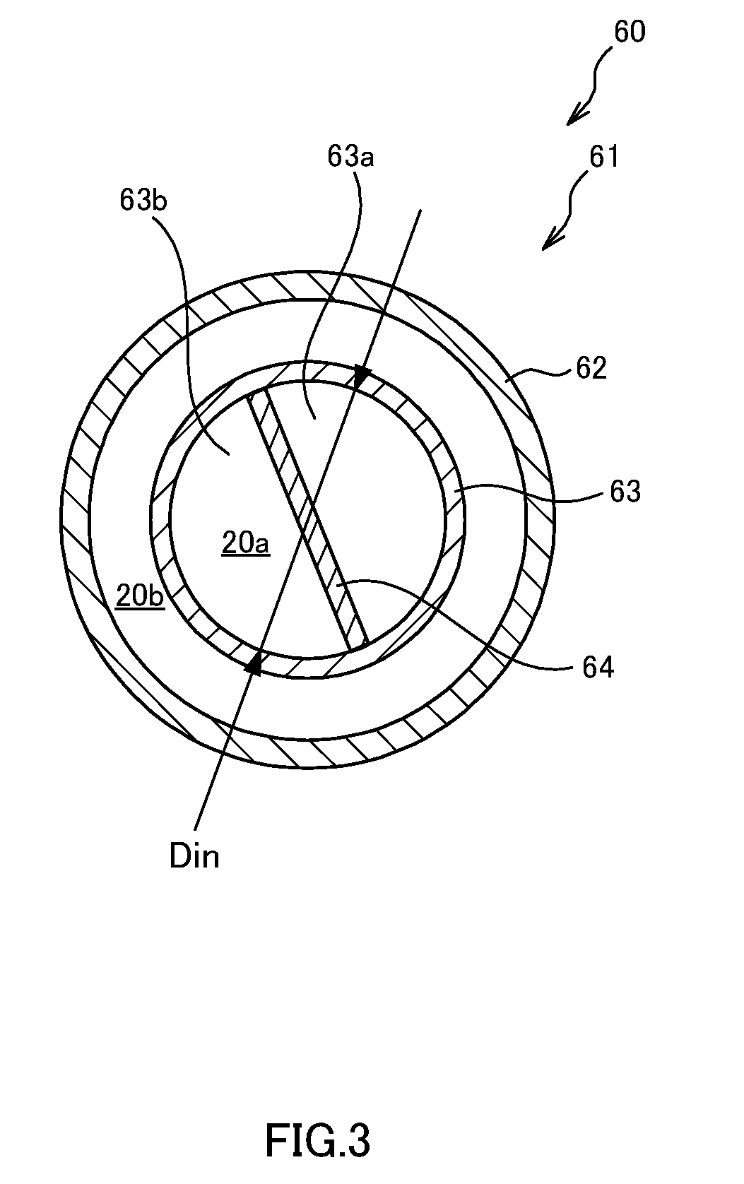
A double pipe includes an inner pipe through an interior of which low pressure gaseous cooling medium flows and an outer pipe having the inner pipe in its interior, the outer pipe being configured such that high-pressure liquid cooling medium flows between the inner pipe and the outer pipe, wherein the inner pipe has a plate member that extending in the longitudinal direction so as to partition the interior of the inner pipe into a plurality of chambers. The plate member has a helical shape along the longitudinal direction.

Description

TECHNICAL FIELD[0001]The present invention relates to a double pipe.BACKGROUND ART[0002]JP4350079B2 discloses a refrigeration cycle device including a double pipe in which two pipes are arranged in a concentric manner. In the double pipe disclosed in JP4350079B2, a low-temperature, low-pressure gaseous cooling medium flows through an interior of an inner pipe, and a high-temperature, high-pressure liquid cooling medium flows through a space between the inner pipe and an outer pipe. Thus, heat exchange is performed between the gaseous cooling medium in the interior of the inner pipe and the liquid cooling medium outside the inner pipe through the inner pipe.SUMMARY OF INVENTION[0003]However, with the double pipe disclosed in JP4350079B2, because the flow speed of the gaseous cooling medium flowing through the interior of the inner pipe is higher in a central portion of the inner pipe than in its surrounding, the flow of the gaseous cooling medium tends to be concentrated to the centr...

Claims


Application Information

Patent Timeline
IPC IPC(8): F28F13/12F28D7/10F28F1/40F25B40/00
CPCF28F13/12F28D7/10F28F1/40F25B40/00F16L9/18
Inventor YOSHIDA, HIROYUKIHATAKEYAMA, JUNOONO, HIROYUKI
Owner MARELLI CABIN COMFORT JAPAN CORPORATION
Learn More