Heat exchanger and air conditioner

A technology for heat exchangers and air-conditioning devices, which is applied in the field of heat exchangers and air-conditioning devices, and can solve the problems that the performance of the condenser cannot be fully obtained.

Active Publication Date: 2015-06-03
DAIKIN IND LTD
View PDF9 Cites 3 Cited by
  • Summary
  • Abstract
  • Description
  • Claims
  • Application Information

AI Technical Summary

Problems solved by technology

[0010] The heat exchangers disclosed in the above-mentioned Patent Documents 1 and 2 have the following problem: if the number of flat tubes is increased to increase the flow rate of the refrigerant, the total header will be longer, and the performance as a condenser cannot be fully obtained.

Method used


Image

  • Heat exchanger and air conditioner
  • Heat exchanger and air conditioner
  • Heat exchanger and air conditioner

Examples


no. 1 approach

[0083] A first embodiment of the present invention will be described. The heat exchanger in this embodiment is the outdoor heat exchanger 23 provided in the air conditioner 10 .

[0084] -Air conditioner-

[0085] refer to figure 1 The air conditioner 10 will be described.

[0086]

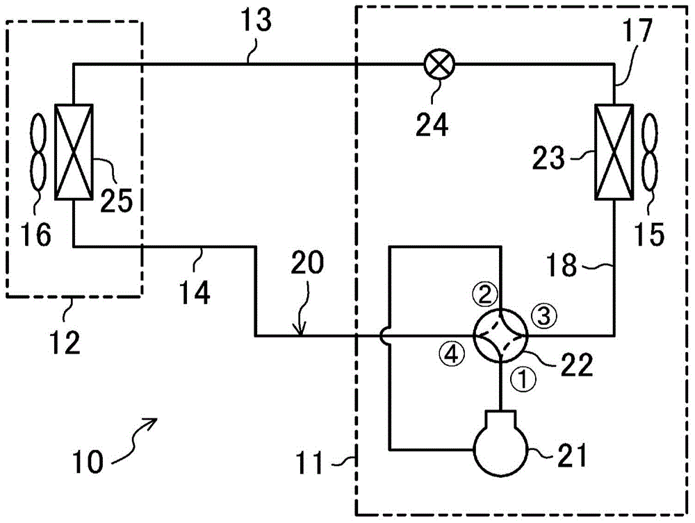
[0087] The air conditioner 10 includes an outdoor unit 11 and an indoor unit 12 . The outdoor unit 11 and the indoor unit 12 are connected to each other via a liquid side connection pipe 13 and a gas side connection pipe 14 . In the air conditioner 10 , a refrigerant circuit 20 is formed by the outdoor unit 11 , the indoor unit 12 , the liquid-side connecting pipe 13 , and the gas-side connecting pipe 14 .

[0088] A compressor 21 , a four-way reversing valve 22 , an outdoor heat exchanger 23 , an expansion valve 24 , and an indoor heat exchanger 25 are provided in the refrigerant circuit 20 . The compressor 21 , the four-way reversing valve 22 , the outdoor heat exchanger 23 and the expans...

no. 2 approach

[0141] A second embodiment of the present invention will be described. This embodiment is obtained by changing the structure of the outdoor heat exchanger 23 of the first embodiment. Here, refer appropriately to Figure 7 and Figure 8 , the difference between the outdoor heat exchanger 23 of this embodiment and the above-mentioned first embodiment will be described.

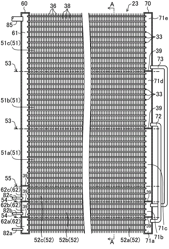
[0142] Such as Figure 7 As shown, the flat tube 33 of the outdoor heat exchanger 23 is vertically divided into an upper heat exchange area 51 and a lower heat exchange area 52 as in the above-mentioned first embodiment. The upper heat exchange area 51 is divided into three main heat exchange parts 51a-51c arranged vertically, and the lower heat exchange area 52 is composed of an auxiliary heat exchange part 52a. That is, in the upper side heat exchange region 51, the first main heat exchange part 51a, the second main heat exchange part 51b, and the third main heat exchange part 51c are formed in this order ...

no. 3 approach

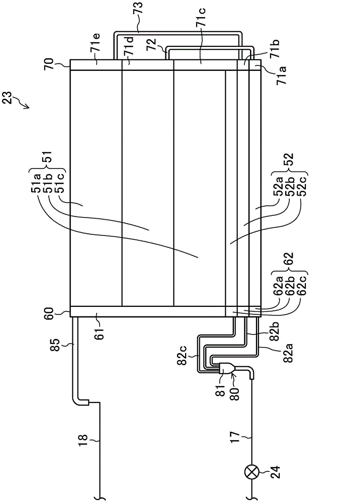
[0163] A third embodiment of the present invention will be described. This embodiment is obtained by changing the structure of the second header 70 of the outdoor heat exchanger 23 of the above-mentioned first embodiment, and the other structures are the same as those of the first embodiment. In this embodiment, appropriately refer to Figure 11 and Figure 12 , only the structure of the second collective header 70 of the outdoor heat exchanger 23 will be described.

[0164] Such as Figure 12 As shown, the inner space of the second collective header 70 of the outdoor heat exchanger 23 is divided into three communicating spaces 71 a - 71 c by two partitions 39 left and right. Specifically, in the inner space of the second collective manifold 70, according to Figure 12 In order from the right side to the left side, a first communication space 71a, a second communication space 71b, and a third communication space 71c are formed. The first communication space 71a communicat...


PUM


Abstract

An upper heat exchange region (51) is divided into a plurality of main heat exchange parts (51a-51c), and a lower heat exchange region (52) is divided into a plurality of auxiliary heat exchange parts (52a-52c). A first header collecting pipe (60) is divided into an upper space (61) corresponding to the upper heat exchange region (51) and a lower space (62) corresponding to the lower heat exchange region (52). The lower space (62) is divided into a plurality of communication spaces (62a-62c) corresponding respectively to the auxiliary heat exchange parts (52a-52c). A second header collecting pipe (70) is divided into a communication space (71c) corresponding to both of the lowermost main heat exchange part (51a) of the upper heat exchange region (51) and the uppermost auxiliary heat exchange part (52c) of the lower heat exchange region (52), and into communication spaces (71 a, 71b, 71d, 71e) corresponding respectively to the other main heat exchange parts (51b, 51c) and the other auxiliary heat exchange parts (52a, 52b). Each of pairs of communication space (71 a, 71b) and communication space (71d, 71e) is connected to an associated one of communication pipes (72, 73).

Description

[0001] This application is based on the divisional application of the invention patent application with the title of the invention "Heat Exchanger and Air Conditioning Device", the application date is January 23, 2012, and the application number is 201280005288.0. technical field [0002] The present invention relates to a heat exchanger comprising a pair of collective collecting pipes and a plurality of flat tubes connected to the respective collective collecting pipes, allowing fluid and air flowing in the flat tubes to exchange heat, and an air conditioner comprising the heat exchanger . Background technique [0003] Heretofore, heat exchangers comprising a pair of headers and a plurality of flat tubes connected to the headers are known. Patent Documents 1 and 2 disclose such heat exchangers. Specifically, in the heat exchangers disclosed in Patent Documents 1 and 2, a collective header is erected at the left end and right end of the heat exchanger, and a plurality of fl...

Claims


Application Information

Patent Timeline
Patent Type & Authority Applications(China)
IPC IPC(8): F28F9/02F28F9/22F28F9/26
CPCF25B39/00F28D1/05391F28D2021/0068F28F1/126F28F9/0209F28F2215/12F28F2250/06F28F9/02F28F9/22F28F9/26F28F9/0275
Inventor 神藤正宪织谷好男藤野宏和镰田俊光
Owner DAIKIN IND LTD
Why Eureka
Try Eureka