
Heat treatment method for tool

A heat treatment method and heat treatment device technology, applied in heat treatment furnaces, heat treatment equipment, manufacturing tools, etc., can solve the problems of not being able to open the heating furnace immediately, not being able to accurately grasp the heating and cooling time, and being inconvenient for operators to operate, so as to avoid The effect of scalding the operator, accurate heating time and quick cooling time, and convenient operation

Active Publication Date: 2018-04-13
ZUNYI ZHONGBO CEMENTED CARBIDE
View PDF4 Cites 4 Cited by
  • Summary
  • Abstract
  • Description
  • Claims
  • Application Information

AI Technical Summary

Problems solved by technology

[0004] In the step b of the heat treatment method of the above-mentioned cemented carbide blade, since the cemented carbide blade heated to 1100-1250° C. in vacuum needs to be rapidly cooled by liquid nitrogen, but the heating furnace cannot be opened immediately after heating and vacuumizing, it is necessary to The heating furnace can only be opened after the heating furnace returns to normal pressure, so the heating and cooling time cannot be accurately grasped; in addition, it is not convenient for the operator to transfer the cemented carbide blade between the heating furnace and the liquid nitrogen cooling device

Method used


Image

  • Heat treatment method for tool

Examples


Embodiment Construction

[0028] The present invention will be described in further detail below by means of specific embodiments:

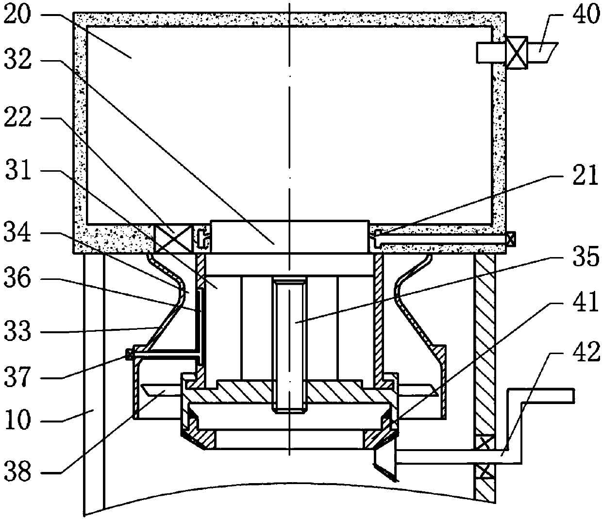
[0029] The reference signs in the drawings of the description include: frame 10, heating box 20, air duct 21, valve 22, quick cooling box 31, tool table 32, Venturi tube 33, throat 34, pull rod 35, liquid nitrogen channel 36 , liquid nitrogen source 37, paddle 38, vacuum machine 40, first bevel gear 41, rotating handle 42, guide rib.

[0030] The tool heat treatment method of the present embodiment comprises the following steps:

[0031] Step (1), immerse the tool in engine oil for three hours, heat it to 500-600°C, and then cool it naturally;

[0032] Step (2), quenching and low-temperature tempering are carried out to the tool.

[0033] Step (2) is carried out using a tool heat treatment device, such as figure 1As shown, the tool heat treatment device includes a frame 10 , a heating box 20 , a quick cooling mechanism, and a vacuum machine 40 connected to the heating ...


PUM


Abstract

The invention relates to the field of metal heat treatment and particularly discloses a heat treatment method for a tool. Quenching and tempering are performed by using a tool heat treatment device. The tool heat treatment device comprises a heating box, a quick-cooling mechanism and a vacuum machine. An opening is formed in the bottom of the heating box. The quick-cooling mechanism comprises a quick-cooling box, liquid nitrogen sources and a tool table only capable of sliding up and down in the quick-cooling box. A rotary disc rotationally connected with the quick-cooling box is arranged on the lower portion of the quick-cooling box. Paddles are fixedly arranged on the circumference of the rotary disc. A pull rod connected with the rotary disc in a threaded manner is fixedly arranged at the bottom of the tool table. The periphery of the quick-cooling box is sleeved with a venturi tube. Air inlets communicating with diffusion sections are formed in the bottom of the heating box. The paddles are arranged in corresponding inlet sections. A valve is arranged at each air inlet. Liquid nitrogen channels are arranged on the side wall of the quick-cooling box. The two ends of each liquidnitrogen channel correspondingly communicate with the corresponding liquid nitrogen source and a throat channel. After the valves are opened, the air flow can suck liquid nitrogen through the liquid nitrogen channels to quickly cool the quick-cooling box; and meanwhile the air flow drives the paddles to rotate, and the tool table quickly slides to the quick-cooling box to quickly cool the tool.

Description

technical field [0001] The invention relates to the field of metal heat treatment, in particular to a tool heat treatment method. Background technique [0002] Coated carbide inserts are now widely used in the field of metal cutting. Although cemented carbide has excellent properties such as high hardness, wear resistance and corrosion resistance when it is used as tool and mold material in machinery, mining, electronics, standard parts and other industries, when it is used as a metal cutting tool, there are reasons The defects of poor toughness that lead to chipping, brittle fracture and early wear failure severely limit the application range of cemented carbide inserts; especially in the case of impact loads, not only high hardness and high wear resistance are required for cemented carbide, It is important that it also has good overall strength and toughness. [0003] Although the existing cemented carbide inserts have solved certain problems, their application is still ...

Claims


Application Information

Patent Timeline
IPC IPC(8): C21D9/22C21D1/18C21D1/773
CPCC21D1/18C21D1/773C21D9/22
Inventor 稽建斌胡筱胡光强赵伟
Owner ZUNYI ZHONGBO CEMENTED CARBIDE
Learn More