Supercharge Your Innovation With Domain-Expert AI Agents!

Multivoltage clock synchronization

A voltage and voltage domain technology, applied in the field of digital computer systems, to achieve the effect of improving distortion

Active Publication Date: 2013-10-09
SYNOPSYS INC
View PDF5 Cites 0 Cited by
  • Summary
  • Abstract
  • Description
  • Claims
  • Application Information

AI Technical Summary

Problems solved by technology

[0009] Embodiments of the invention address the problem of having to add a delay to the low voltage clock in order to align the low voltage clock with the high voltage clock

Method used


Image

  • Multivoltage clock synchronization
  • Multivoltage clock synchronization
  • Multivoltage clock synchronization

Examples


Embodiment Construction

[0024] Although the invention has been described in connection with one embodiment, the invention is not intended to be limited to the specific forms presented. On the contrary, it is intended to cover such alternatives, modifications and equivalents as may be reasonably included within the scope of the invention as defined by the appended claims.

[0025] In the following detailed description, numerous specific details have been given, such as specific method sequences, structures, elements, and connections. It is understood, however, that these and other specific details need not be utilized to practice embodiments of the invention. In other instances, well-known structures, elements, or connections have been omitted or not described in particular detail in order to avoid unnecessarily obscuring the description.

[0026] References in this specification to "one embodiment" or "an embodiment" are intended to indicate that a specific feature, structure, or characteristic desc...


PUM


Abstract

A level converter circuit is disclosed. The level converter circuit includes a first level converter that generates a first output signal, and a second level converter that generates a second output signal. The level converter circuit further includes an edge selector coupled to the first level converter and the second level converter that selects a rising edge of either the first output signal or the second output signal, and selects a falling edge of either the first output signal or the second output signal to generate an optimized output signal.

Description

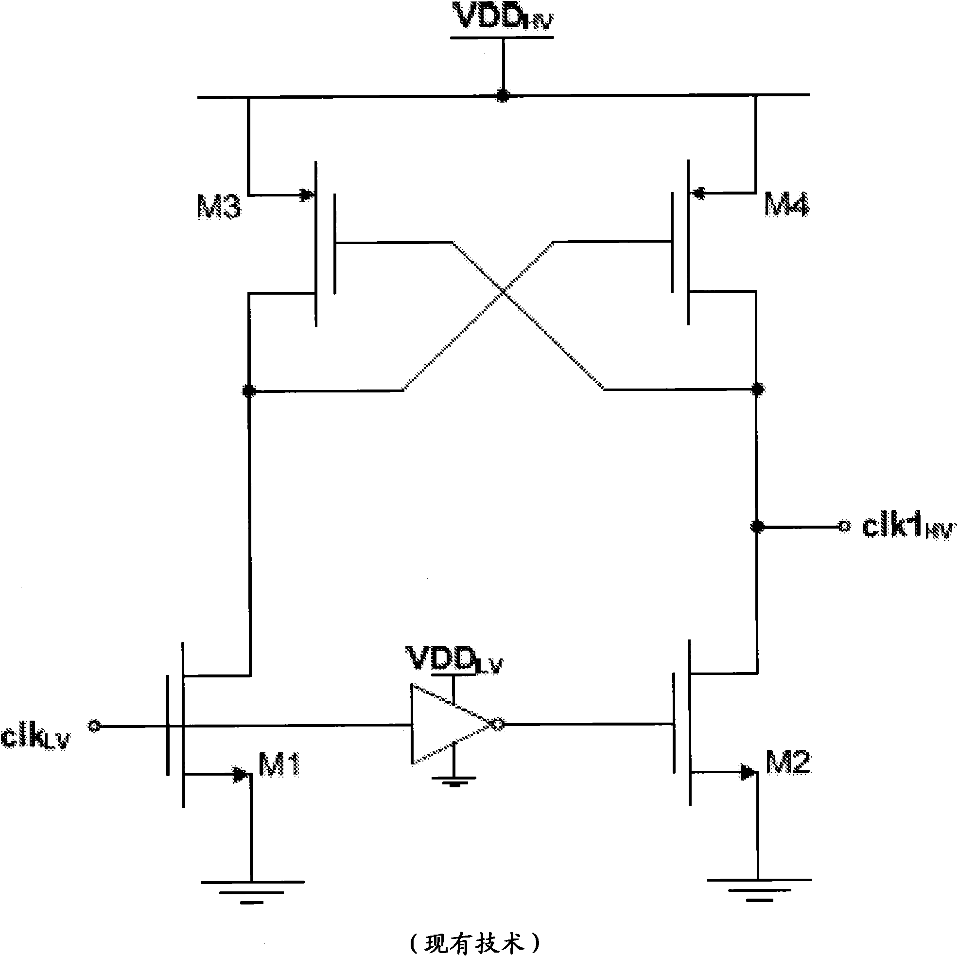
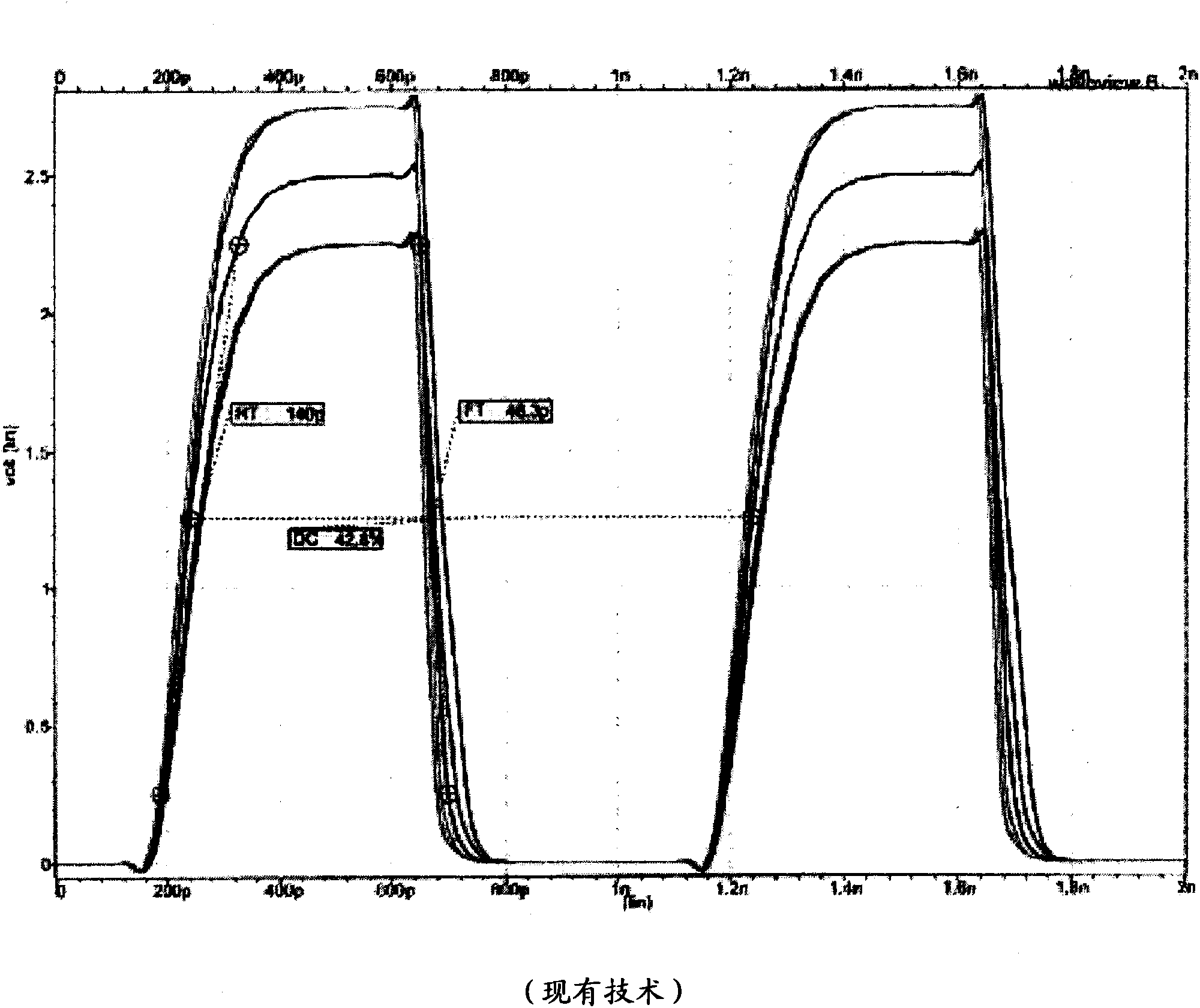
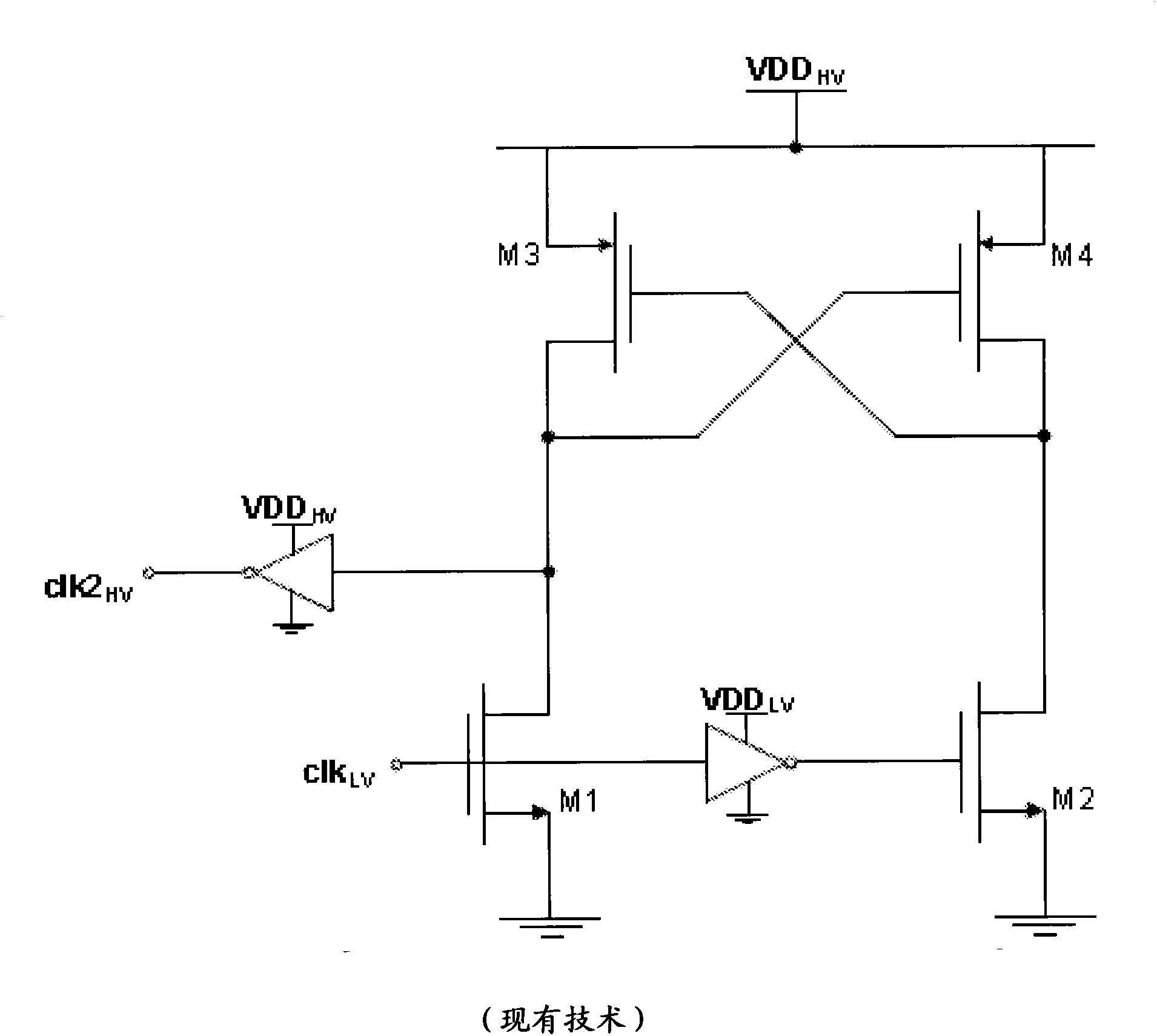
technical field [0001] The present invention relates generally to digital computer systems. Background technique [0002] Analog circuits often need to distribute clock signals to multiple voltage domains throughout their operation. A common situation is in CMOS analog-to-digital converters (ADCs) used in communication and video systems, where the input sampling switch is in the 2.5 / 3.3 volt domain and the core of the ADC is in the 1.2 volt domain. These two clock domains must be well aligned to allow high frequency operation with low sampling jitter and distortion. In fact, this misalignment is often one of the main sources of distortion in high speed ADCs. Under certain conditions, it may even be the decisive factor. [0003] figure 1 The circuit of ® is typically used to transfer the clock signal from the 1.2V domain (LV-low voltage) to the 2.5V or 3.3V domain (HV-high voltage). The PMOS transistors (M3 / M4) must be weaker than the underlying NMOS (M1 / M2) for proper o...

Claims


Application Information

Patent Timeline
Patent Type & Authority Applications(China)
IPC IPC(8): H03K19/096
CPCG06F1/10
Inventor P·M·费雷拉德菲格雷多
Owner SYNOPSYS INC
Features
  • R&D
  • Intellectual Property
  • Life Sciences
  • Materials
  • Tech Scout
  • Unparalleled Data Quality
  • Higher Quality Content
  • 60% Fewer Hallucinations
Learn More