Upper punching structure for continuous deep drawing or molding die

A forming mold and stretching forming technology, which is applied in the direction of perforating tools, manufacturing tools, metal processing equipment, etc., can solve the problems of unstable difficulty, affecting the normal operation of the mold, increased stretching or forming, etc., to achieve guaranteed strength and effective compression The effect of material area

Inactive Publication Date: 2013-10-16
厦门锐腾电子科技有限公司
View PDF10 Cites 3 Cited by
  • Summary
  • Abstract
  • Description
  • Claims
  • Application Information

AI Technical Summary

Problems solved by technology

However, for some products, such as electronic lead frames, it needs to be stretched or formed first, and then punched. The direction of stretching or forming has to be changed, but such a mold structure changes the already stable and recognized stretching or forming direction, and it will add difficulty or unstable factors to stretching or forming
[0003] The discharge of waste after punching of continuous stretching or forming molds is a major problem in the industry. Since the waste cannot be discharged in time, it affects the normal operation of the mold

Method used


Image

  • Upper punching structure for continuous deep drawing or molding die
  • Upper punching structure for continuous deep drawing or molding die
  • Upper punching structure for continuous deep drawing or molding die

Examples


Embodiment

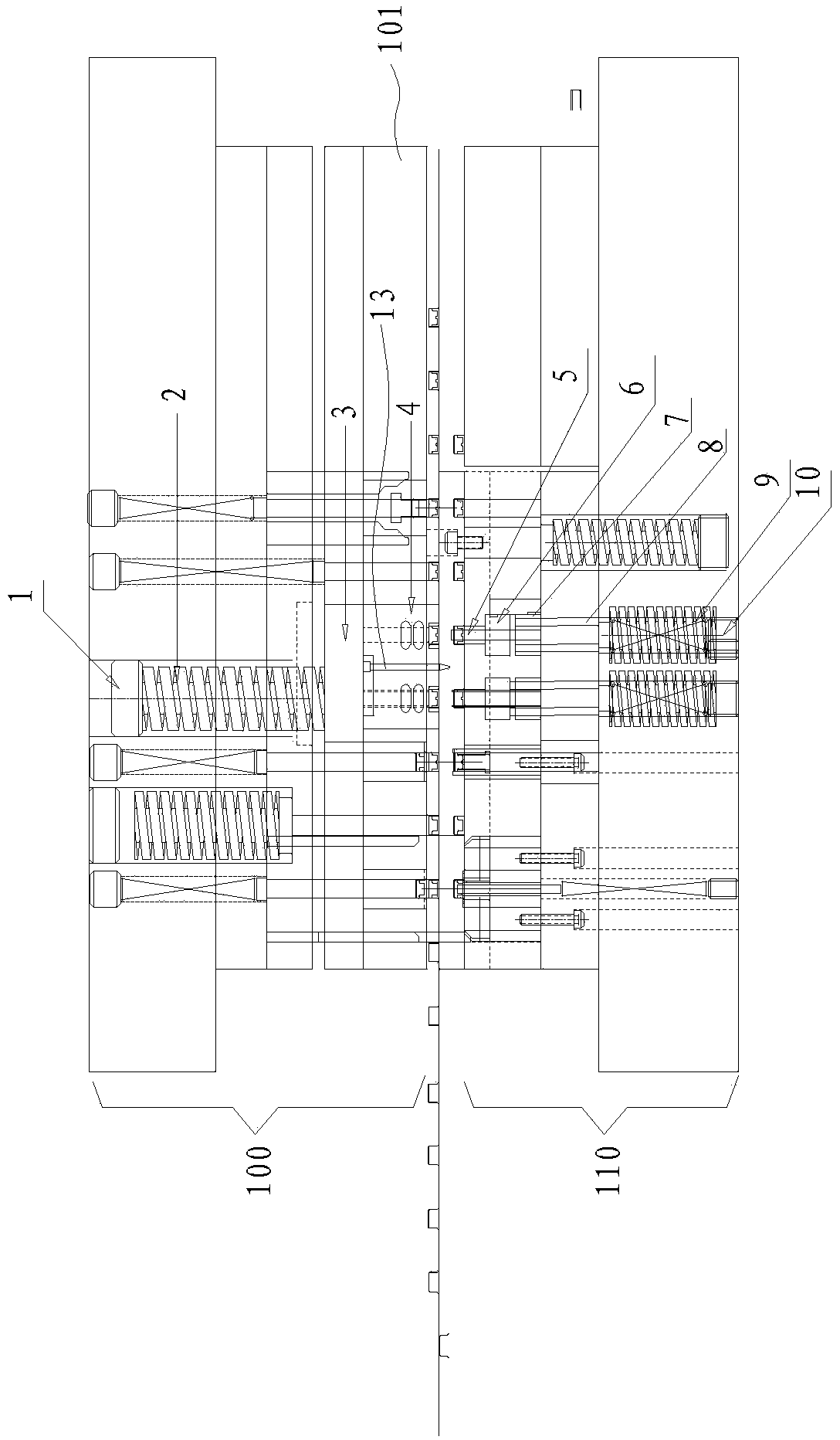
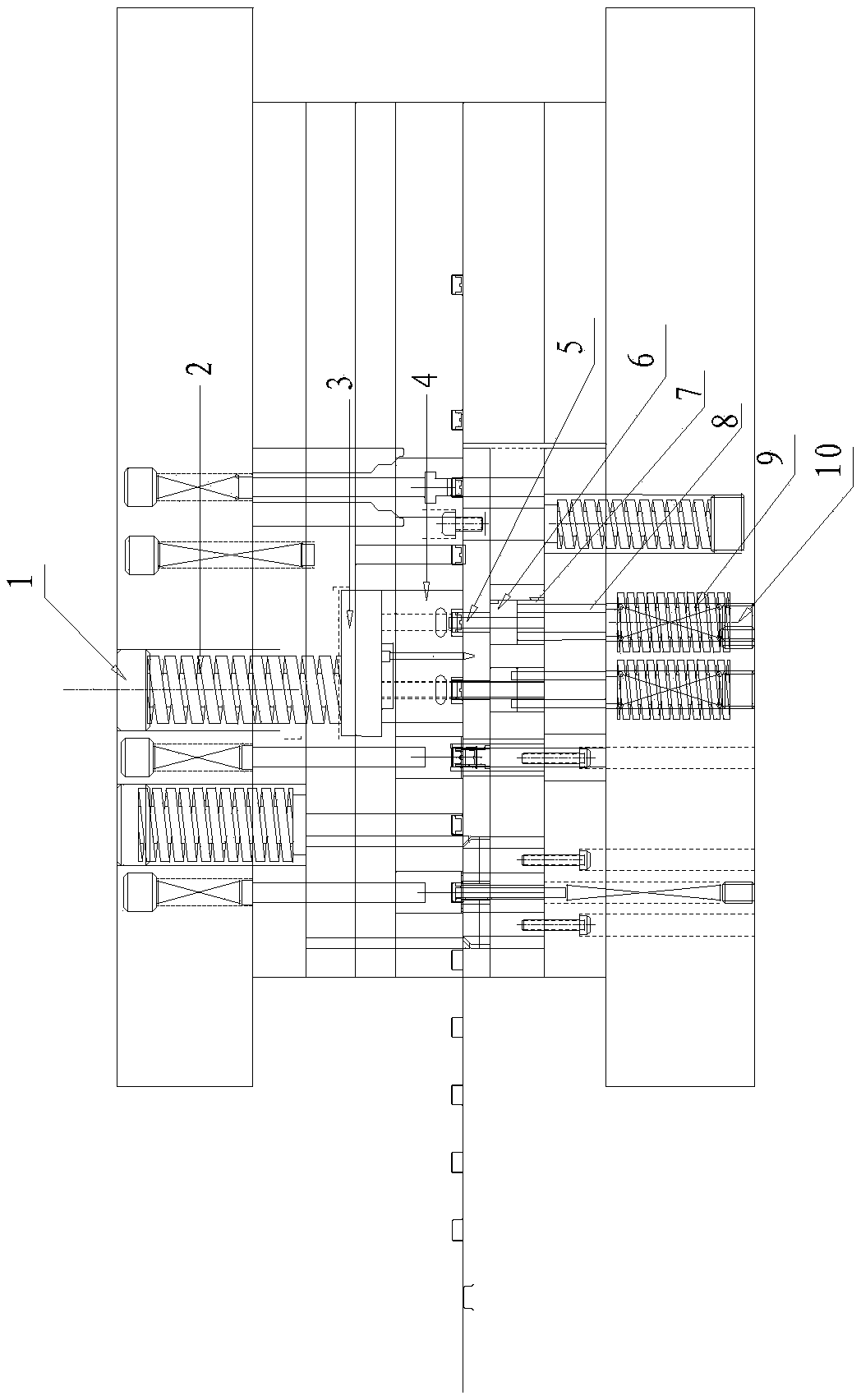
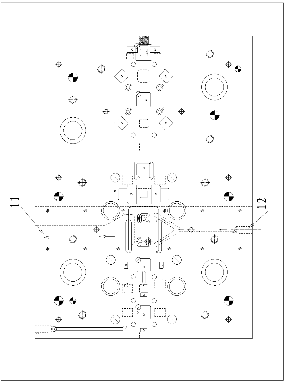
[0020] Example: see Figure 1 to Figure 3 , an upper punching structure for continuous drawing or forming moulds, comprising a stretch forming upper die 100 and a stretch forming lower die 110, a punching punch 5 is installed on the stretch forming lower die 110, and a stretch forming upper die 100 The punching die 4 corresponding to the punching punch 5 is installed, and the stretch forming lower die 110 is provided with a punching and stripping block 6 and is passed through by the punching punch 5, and the punching and stripping block 6 is formed by a stripping spring 9 is lifted by the power transmission pin 8, and the punching and stripping block 6 is pressed down by the punching die 4 when the mold is closed, so that the punching punch 5 protrudes and cooperates with each other to complete the upper punching operation after stretching and forming. A blowing passage is provided between the upper and lower molding dies, and the passage communicates with the punching die cav...


PUM


Abstract

The invention discloses an upper punching structure for a continuous deep drawing or molding die. The upper punching structure comprises a drawing molding upper die and a drawing molding lower die, wherein the drawing molding lower die is provided with a punching male die, the drawing molding upper die is provided with a punching female die corresponding to the punching male de, when in die assembly, a punching material removing block is pressed down by the punching female die so that the punching male die stretches out to cooperate with the punch female die so as to complete upper punching operation after drawing molding. Under the premise of not changing the original drawing or molding direction, the punching direction is changed so as to guarantee the strength of the punching female die to guarantee the die to be produced stably, the problem of waste discharge is solved through a blowing manner, and the upper punching structure has the advantages of reasonable structure, stability in product machining, and the like.

Description

technical field [0001] The invention discloses an upper punching structure for a continuous drawing or forming mold, which belongs to the technical field of continuous mold manufacturing according to the International Patent Classification (IPC). Background technique [0002] Traditional mold punching generally adopts the way of punching down, that is, the punch moves up and down to realize the punching operation, while the continuous die usually uses the way of punching down, such as the Chinese document CN201210393450.2 Punch continuous die, including An upper mold, a lower mold and a base, the upper mold is provided with punches for punching, the lower mold is provided with inner guide posts, and the lower mold is provided with punching holes corresponding to the punches. However, for some products, such as electronic lead frames, it needs to be stretched or formed first, and then punched. The direction of stretching or forming has to be changed, but such a mold structur...

Claims


Application Information

Patent Timeline
Patent Type & Authority Applications(China)
IPC IPC(8): B21D28/24B21D28/34B21D45/06
Inventor 杨国福
Owner 厦门锐腾电子科技有限公司
Why Eureka
Try Eureka