
Continuous casting billet laser sizing system

A continuous casting billet and sizing technology, which is applied in the field of continuous casting billet laser sizing system, can solve the problems of complicated installation, debugging, operation and maintenance, low sizing accuracy, etc., and achieves simple installation, debugging, operation and maintenance, and high sizing accuracy. , the effect of low operating costs

Active Publication Date: 2013-10-16
江阴福盛自动化仪表有限公司
View PDF4 Cites 17 Cited by
  • Summary
  • Abstract
  • Description
  • Claims
  • Application Information

AI Technical Summary

Problems solved by technology

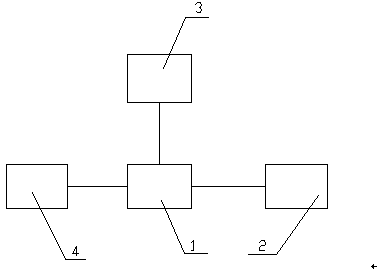
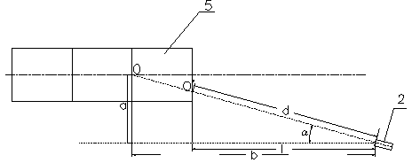
[0005] In order to solve the problems of low sizing accuracy, complex installation, commissioning and operation and maintenance of the current continuous casting slab sizing device, the present invention provides a continuous casting slab laser sizing system, including controlling the roller table of the continuous casting machine and flame cutting The PLC unit of the machine; it is set on the side front of the continuous casting billet and connected with the PLC unit, and is used to detect the relative position of the continuous casting billet. The laser detection unit is located above the roller surface of the continuous casting billet conveying roller table In the horizontal plane of half the thickness of the continuous casting slab; connected with the PLC unit, it is used to monitor the operation of the entire system and provide a display unit for manual input of necessary data during debugging; connected with the PLC unit, it is used to detect the laser detection unit The calculation unit for converting the relative position of the end face of the continuous casting slab into the actual length of the continuous casting slab

Method used


Image

  • Continuous casting billet laser sizing system
  • Continuous casting billet laser sizing system

Examples


Embodiment Construction

[0012] All features disclosed in this specification, or steps in all methods or processes disclosed, may be combined in any manner, except for mutually exclusive features and / or steps.

[0013] Any feature disclosed in this specification, unless specifically stated, can be replaced by other equivalent or similar purpose alternative features. That is, unless expressly stated otherwise, each feature is one example only of a series of equivalent or similar features.

[0014] Such as figure 1 The continuous casting slab laser sizing system shown includes a PLC unit 1 that controls the roller table of the continuous casting machine and the flame cutting machine; a laser detection unit 2 connected to the PLC unit for detecting the relative position of the continuous casting slab; and a PLC unit Connected to the display unit 3 for monitoring the operation of the entire system and manually inputting necessary data during debugging; connected to the PLC unit for converting the relativ...


PUM


Abstract

The invention discloses a continuous casting billet laser sizing system. The continuous casting billet laser sizing system comprises a PLC unit, a laser detection unit, a display unit and a calculation unit, wherein the PLC unit controls a roller bed of a continuous casting machine and a flame cutting machine; the laser detection unit is connected with the PLC unit and is used for detecting relative positions of continuous casting billets; the display unit is connected with the PLC unit and is used for monitoring operating conditions of the whole system and allowing workers to input necessary data during debugging; the calculation unit is connected with the PLC unit and is used for converting the relative positions, detected by the laser detection unit, of end surfaces of the continuous casting billets into actual lengths of the continuous casting billets. The continuous casting billet laser sizing system has the advantages of being high in sizing precision, stable and simple in calibration, easy to install, debug, operate and maintain, low in operation cost and accurate in cutting, improves sizing rate and yield and reduces rejection rate.

Description

technical field [0001] The invention relates to the field of continuous casting machinery and equipment, in particular to a continuous casting slab laser sizing system. Background technique [0002] In the production process of continuous casting machines in metallurgical enterprises, the precision of continuous casting slab sizing directly affects the output, product quality and cost of continuous casting machines. With the change of the market and the improvement of the quality requirements of continuous casting slabs, the pressure of cost is increasing, the specifications of cut-to-length are more and more, and the requirements for the accuracy of cut-to-length are getting higher and higher, especially for full-length production and continuous casting The implementation of billet hot-feeding process puts forward stricter requirements for continuous casting billet cut-to-length. [0003] At present, there are mainly three cut-to-length methods for continuous casting machi...

Claims


Application Information

Patent Timeline
Patent Type & Authority Applications(China)
IPC IPC(8): B22D11/126B22D11/16
Inventor 龚吉文
Owner 江阴福盛自动化仪表有限公司
Learn More