Integrated preform injection mould for PP large volume parenteral stationary ring

An injection mold and large infusion technology, which is applied in the field of PP large infusion suspension ring integrated bottle preform injection mold, can solve the problems of increased labor loss, increased mold cost, and loss of suspension rings, etc., to reduce energy and welding losses and reduce manufacturing costs. Reduce and reduce the effect of forming molds

Active Publication Date: 2015-06-10
CHENGDU LIANYU PRECISION MACHINERY
View PDF6 Cites 0 Cited by
  • Summary
  • Abstract
  • Description
  • Claims
  • Application Information

AI Technical Summary

Problems solved by technology

However, if the ring and the infusion bottle are formed on different molds, molds with different structures are required, which increases the cost of the mold, increases the area of ​​the production plant, and greatly increases the labor loss, and the production process becomes more complicated. process, there are many production processes, and it is easy to produce pollution
[0003] Chinese patent 200810072900.1 discloses the process of welding rings in the blowing of plastic infusion bottles. During the heating period in the preform blowing process, the hanging rings are welded by ironing device, heat preservation and other processes, and the bottle is blown at the same time. The bottom of the infusion bottle is prone to welding stress and weak welding, while the infusion bottle filled with injection is heavy, and the hanging ring is prone to fall off; in addition, the welding process increases the production time, reduces production efficiency, and pollutes the environment

Method used


Image

  • Integrated preform injection mould for PP large volume parenteral stationary ring
  • Integrated preform injection mould for PP large volume parenteral stationary ring
  • Integrated preform injection mould for PP large volume parenteral stationary ring

Examples


Embodiment Construction

[0021] The present invention will be further described below in conjunction with the drawings, but the protection scope of the present invention is not limited to the following.

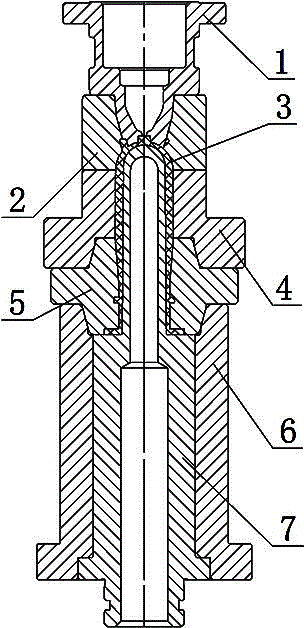
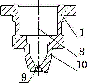
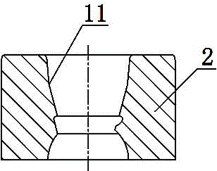
[0022] Such as Figure 1 to Figure 7 As shown, the PP large infusion ring integrated preform injection mold includes a gate mold core 1, a bottom mold 2, a cavity 4, a mold lip 5, a core sleeve 6 and a core 7, and the gate mold core 1 is opened inside There is a pouring melting cavity 8, the bottom of the pouring melting cavity 8 is provided with a glue injection port 9, the lower part of the gate mold core 1 is provided with a mold core matching surface 10; the bottom mold 2 is provided with a mold core matching groove 11, a mold core matching groove 11 is matched with the mold core mating surface 10, the cavity 4 is arranged under the bottom mold 2, the upper part of the inner side of the cavity 4 is provided with a cavity through hole 12, and the lower part of the inner side of the cavity 4 is provid...


PUM


Abstract

The invention relates to an integrated preform injection mould for a PP large volume parenteral stationary ring, which comprises a sprue mold insert (1), a bottom mold (2), a mold cavity (4), a mold lip (5), an injection core sleeve (6) and an injection core (7), wherein a pouring melting cavity is formed in the inside of the sprue mold insert (1); a glue injection hole is formed in the bottom of the pouring melting cavity; the mold cavity (4) is arranged at the lower part of the bottom mold (2); a mold cavity through hole is formed in the upper part of the inner side of the mold cavity (4); the lower side of the mold lip (5) is sleeved with the injection core sleeve (6); an injection core sleeve through hole is formed inside the injection core sleeve (6); the injection core (7) is sleeved with the injection core sleeve through hole; the upper part of the injection core (7) penetrates a mold lip through hole and the mold cavity through hole in sequence, and extends to the lower part of the bottom mold (2); the space formed by the bottom of the sprue mold insert (1), the bottom mold (2), the mold cavity (4), the mold lip (5), and the injection core (7) in a matching manner is a preform molding cavity (3). The integrated preform injection mould has the advantages that the manufacture cost is low, the positioning precision is high and the production efficiency is high.

Description

Technical field [0001] The invention relates to an injection mould for an infusion bottle, in particular to an injection mould for a preform with an integrated PP large infusion ring. Background technique [0002] At present, plastic infusion bottles have been widely used, and the bottom of the plastic infusion bottle needs a hoisting ring, which is convenient to hang on a fixed hook during use. The infusion bottle lifting ring structure produced by the existing mold includes the lifting ring, the infusion bottle connector and the infusion bottle. The infusion bottle connector connects the lifting ring and the infusion bottle. The infusion bottle connector is fixedly connected to the bottom of the infusion bottle by welding. During transportation Stick the lifting ring on the bottom of the infusion bottle to be flush with the infusion bottle connector; when in use, the lifting ring can be hung on the infusion stand. While the rings and the infusion bottle are formed on different...

Claims


Application Information

Patent Timeline
Patent Type & Authority Patents(China)
IPC IPC(8): B29C45/26
Inventor 王巍陈斌
Owner CHENGDU LIANYU PRECISION MACHINERY
Why Eureka
Try Eureka