Motor train unit traction system adopting catenary and energy storing devices for hybrid power supply

An energy storage device and hybrid power supply technology, applied in mechanical energy storage traction, capacitor traction, battery/battery traction, etc., can solve problems such as energy waste, failure to perform self-rescue in time, and braking energy consumption

Active Publication Date: 2013-10-16
CRRC CHANGCHUN RAILWAY VEHICLES CO LTD
View PDF5 Cites 46 Cited by
  • Summary
  • Abstract
  • Description
  • Claims
  • Application Information

AI Technical Summary

Problems solved by technology

All EMUs with single electric traction cannot meet the requirements of running on non-electrified railways, and cannot perform self-rescue in time when the electrified section fails or the high-voltage system of the vehicle itself fails
[0003] In addition, in the current non-electrified road sections, the traditional centralized power supply trains use the thermal power source, that is, the centralized power supply traction of internal combustion locomotives. During the braking process, the braking energy is mainly consumed by braking resistors, resulting in a huge waste of energy.

Method used


Image

  • Motor train unit traction system adopting catenary and energy storing devices for hybrid power supply
  • Motor train unit traction system adopting catenary and energy storing devices for hybrid power supply
  • Motor train unit traction system adopting catenary and energy storing devices for hybrid power supply

Examples


Embodiment Construction

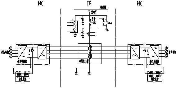
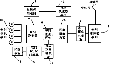
[0020] refer to figure 1 , the embodiment of the present invention mainly includes a traction transformer, an energy storage device, a traction converter and a traction motor. The converter drives the traction motor. The function of the traction transformer is to step down the single-phase network voltage of the AC catenary as the input voltage of the traction converter. The traction converter then drives the traction motor to realize the traction of the EMU. The DC bus between the energy storage device and the traction converter connected.

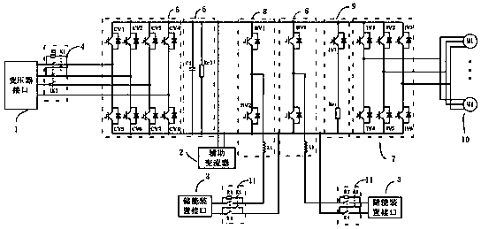
[0021] refer to figure 2 , image 3 , 1-traction transformer interface; 2-auxiliary converter interface; 3-energy storage device interface; 4-first pre-charging device; 5-four-quadrant rectifier; 6-intermediate DC link; 7-traction inverter; 8 -Bidirectional DC / DC chopper; 9-overvoltage suppression circuit; 10-traction motor interface; 11-second pre-charging device

[0022] The traction transformer interface 1 is connected to the inp...


PUM


Abstract

A motor train unit traction system adopting a catenary and energy storing devices for hybrid power supply is characterized by mainly comprising a traction transformer, the energy storing devices, traction converters and traction motors, wherein the catenary is connected with a primary side of the traction transformer through a pantograph, and two secondary side windings of the traction transformer are directly connected with the traction converters which are connected with the traction motors; and the energy storing devices are connected with direct current buses in the middles of the traction converters. The motor train unit traction system can simultaneously operate on an electrification line and a non-electrification line, and the braking energy is absorbed through the energy storing devices under the working condition without the catenary, so that cyclic utilization of the energy is realized, and a green energy saving idea is reflected. Under special rainy or snowy weather or when the catenary is damaged, the motor train unit traction system has emergency rescue and readiness functions, and the energy storing devices can also be used as portable power sources.

Description

technical field [0001] The invention relates to a traction system of an EMU, in particular to an electric traction system of an EMU in which catenary and an energy storage device are mixed to supply power. Background technique [0002] The traction system is the core of the transmission system of the EMU, and it shoulders the task of providing driving power for the train. The traditional EMU traction system is mainly a single electric traction, which adopts catenary power supply mode and can only run on electrified railways. According to my country's railway planning, by the end of 2012, my country's electrified railways accounted for 53% of the country's railway lines; according to the "Medium and Long-Term Railway Network Planning", it is estimated that by 2020, electrified railways will account for 60% of the country's railway lines, and non-electrified railways will still a large proportion for a long time. All EMUs with single electric traction cannot meet the requirem...

Claims


Application Information

Patent Timeline
Patent Type & Authority Applications(China)
IPC IPC(8): B60L9/00B60L11/18
CPCY02T10/7241Y02T10/7005B60L9/24B60L9/28B60L15/32B60L2200/26B60L2210/10B60L2210/20B60L2210/30B60L2210/40B60L2220/42B60L50/30B60L50/40B60L50/51B60L50/53H02M3/155H02M5/297Y02T10/64Y02T10/70Y02T10/72
Inventor 赵明花李军王成涛荀玉涛李雪飞韩伟况阳哈大雷解枫周勇志马昭钰翟黎渊刘俊明万争田伟翟丽佳王颖超蒋英智张金龙金鑫
Owner CRRC CHANGCHUN RAILWAY VEHICLES CO LTD
Why Eureka
Try Eureka