
Deformable connection structure between concrete trestle steps and floors

A concrete and trestle technology, applied in the direction of stairs, etc., to achieve the effect of standard installation, simple construction and material saving

Active Publication Date: 2016-08-17
内蒙古电力勘测设计院有限责任公司
View PDF7 Cites 0 Cited by
  • Summary
  • Abstract
  • Description
  • Claims
  • Application Information

AI Technical Summary

Problems solved by technology

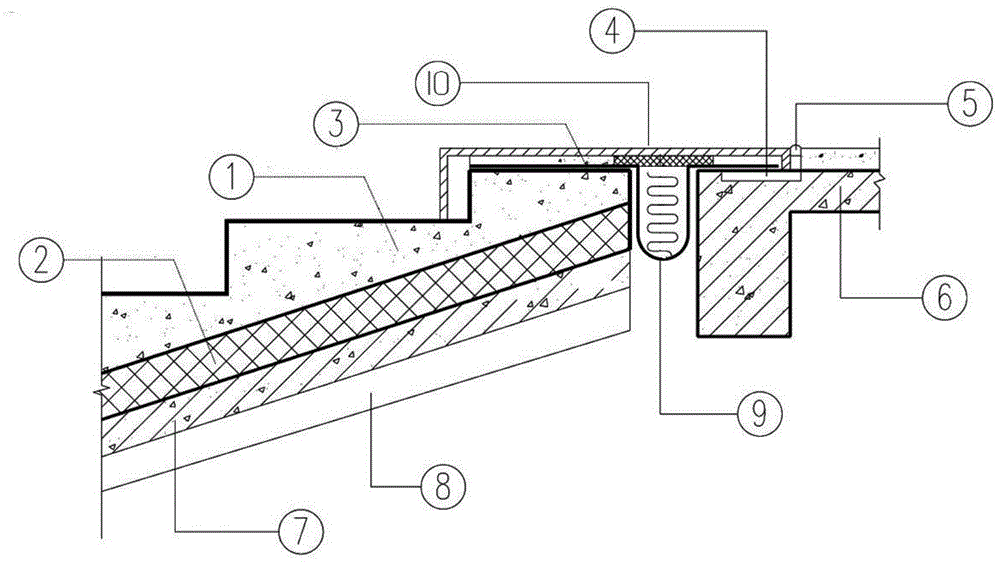
[0004] The main purpose of the present invention is to propose a brand-new deformable connection structure between the steps of the concrete trestle and the floor under the existing technical conditions, so as to solve the deformable and waterproof connection between the steps of the concrete trestle and the floor in the project

Method used


Image

  • Deformable connection structure between concrete trestle steps and floors

Examples


Embodiment Construction

[0017] The present invention will be further described below in conjunction with accompanying drawing.

[0018] When the steps of the concrete trestle bridge are connected with the floor, the connection at the joints can be carried out by the following steps.

[0019] (1) The trestle step structure is a layered structure, the bottom layer is a steel beam 8, on which a trestle floor 7 is arranged, and a layer of thermal insulation material 2 is laid on the trestle floor 7, and the concrete step structure 1 is laid on top of the thermal insulation material 2.

[0020] (2) Place embedded iron pieces 4 on the beams of the floor slab. The embedded iron pieces 4 are square iron sheets of 100mmx100mm, and are placed in grooves on the beams of the floor slab. The distance between the embedded iron pieces 4 is 500mm.

[0021] (3) After the construction of the trestle steps is completed, there is a certain distance between the deformation joints and the floor 6. First, the No. 26 galva...


PUM


Abstract

A deformable connection structure between the steps of the concrete trestle and the floor, wherein the steps of the trestle are structured in a layered structure, and pre-embedded iron pieces are placed on the beams of the floor; deformation joints at a certain distance are left between the steps of the trestle and the floor; It is installed on the upper surface of the concrete step structure and the floor slab; the iron sheet forms a U-shaped structure in the deformation joint, and the U-shaped iron sheet extends in the deformation joint; the U-shaped iron sheet is filled with asphalt hemp; the asphalt hemp is paved with asphalt Wood wool board; cement mortar cushion is laid on the iron sheet; shaped steel plate is covered on the cement mortar cushion, and the end of the steel plate near the floor is welded and fixed with the embedded iron parts; a transverse gap is reserved between the steel plate and the floor; The gap is sealed with polyurethane sealing material after welding. The invention can meet the demand for deformation joints in large-scale projects, and at the same time play the roles of settlement, shockproof, expansion and contraction, and improve waterproof performance.

Description

technical field [0001] The invention relates to a building wall connection structure, in particular to a deformable connection structure between concrete trestle steps and floors. Background technique [0002] Trestle is a station, port, mine or factory, used for loading and unloading goods or getting on and off passengers, or a temporary bridge structure specially used for construction site traffic, mechanical layout and overhead operations. In civil engineering, temporary bridge facilities built for transporting materials, equipment, and personnel are divided into wooden trestle bridges and steel trestle bridges according to the materials used. The trestle in a railway ferry is a bridge building for rolling stock to drive on and off the ferry. [0003] At present, the trestle structure composed of steel structure and concrete is widely used in railway engineering, tunnel construction, electric power engineering and other fields. Since the preforming can only be formed in...

Claims


Application Information

Patent Timeline
Patent Type & Authority Patents(China)
IPC IPC(8): E04F11/02
Inventor 张轩郑平吴璇
Owner 内蒙古电力勘测设计院有限责任公司
Learn More