Side roll device of four-roll plate bending roll

A four-roller plate rolling machine and side roller technology, which is applied in the field of plate rolling machines, can solve the problems of large span of side rollers, failing to meet the requirements of rolling, and difficulty in guaranteeing the rolling accuracy of workpieces.

Inactive Publication Date: 2013-10-23
张瑞瑞
View PDF0 Cites 1 Cited by
  • Summary
  • Abstract
  • Description
  • Claims
  • Application Information

AI Technical Summary

Problems solved by technology

[0002] The current four-roll plate rolling machine generally does not have a support roll for the side roll, so that the load on the side roll during work will cause the deflection of the side roll to change, which may not meet the rolling requirements, or the support roll adopts simply supported beams or cantilever In this way, the life of the backup roll is short, which affects the normal use and life of the plate rolling machine. When the side roll is raised and lowered, the direction of the force on the side roll will also change. The direction of the backup roll remains unchanged, and the working load on the side roll cannot be effective. transmitted to the support roller, and the deflection of the side roller also changes
For the rolled plate with a large width, the span of the side roller is large, the deflection and deformation are large, and the rolling accuracy of the workpiece is difficult to guarantee

Method used


Image

  • Side roll device of four-roll plate bending roll
  • Side roll device of four-roll plate bending roll
  • Side roll device of four-roll plate bending roll

Examples


Embodiment Construction

[0012] The present invention will be described in detail below in conjunction with the accompanying drawings.

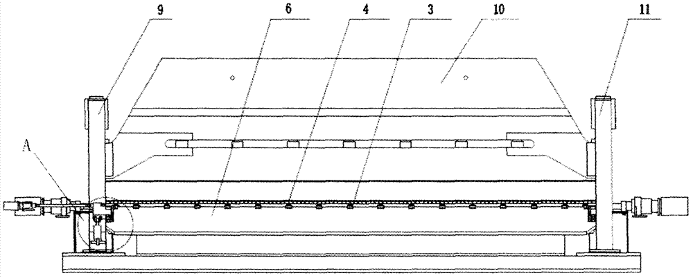
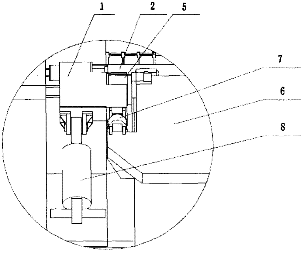
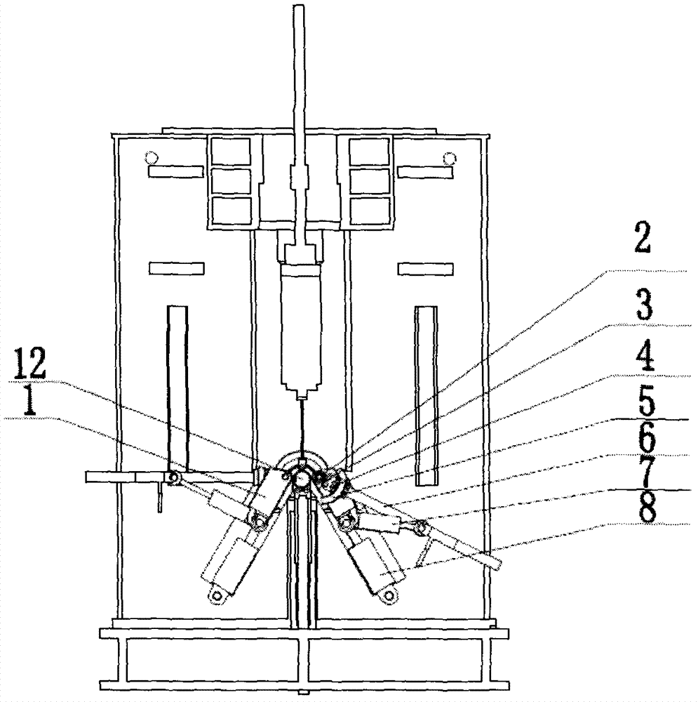
[0013] see figure 1 , figure 2 with image 3 , the upper beam 10 of the four-roll plate bending machine is located between the left frame 9 and the right frame 11, the lower roll 12 is located directly below the upper beam 10, and the side rolls 2 are located on both sides of the lower roll 12.

[0014] The side roll 2 is located on the side roll bearing seat 1, the side roll oil cylinder 8 is connected with the side roll bearing seat 1, and the side roll oil cylinder 8 is installed in the grooves of the left frame 9 and the right frame 11, and the grooves on the left and right frames are eight Glyph, the angle between the groove and the vertical force direction is 30 degrees, and the side roller bearing housing 1 can move along the groove under the action of the side roller cylinder 8, and the work of the side roller cylinder 8 can make the side roller 2 move alo...


PUM


Abstract

The invention relates to a side roll device of a four-roll plate bending roll. The side roll device comprises a side roll bearing seat, a side roll on the side roll bearing seat, and a side roll oil cylinder connected with the side roll bearing seat, and further comprises a side roll support beam, wherein the upper side and the lower side of the side roll support beam are respectively connected with side roll support beam oil cylinders and the side roll bearing seat through side roll support beam curved plates; at least two support roll seats are arranged between the side roll and the side roll support beam in the length direction; a pair of side roll support rolls are arranged on each support roll seat and are tangent to the side roll. When the side roll device works, with the side roll support beam oil cylinders, the side roll support beam moves along the side roll support beam curved plates, or rotates around the side roll, and changes the direction at any time with the change of the stressed direction of the side roll, and as a result, the working load of the side roll is effectively transmitted to the side roll support beam through the side roll support rolls, which in turn reduces the deflexion deformation of the side roll and ensures the bending precision of workpieces.

Description

technical field [0001] The invention relates to a plate rolling machine, in particular to a side roll supporting device of a four-roll plate rolling machine. Background technique [0002] The current four-roll plate rolling machine generally does not have a support roll for the side roll, so that the load on the side roll during work will cause the deflection of the side roll to change, which may not meet the rolling requirements, or the support roll adopts simply supported beams or cantilever In this way, the service life of the support roll is short, which affects the normal use and life of the plate rolling machine. When the side roll is raised and lowered, the direction of the force on the side roll will also change. The direction of the support roll remains unchanged, and the working load on the side roll cannot be effective. The ground is transmitted to the support roller, and the deflection of the side roller also changes. For the rolled plate with a large width, the...

Claims


Application Information

Patent Timeline
Patent Type & Authority Applications(China)
IPC IPC(8): B21C47/02
Inventor 张瑞瑞王强
Owner 张瑞瑞
Why Eureka
Try Eureka