Transmission spindle with buffer

A technology for driving spindles and spindles, which is applied to components with teeth, belts/chains/gears, portable lifting devices, etc. It can solve the problems of high noise, large impact, and easy damage to the transmission mechanism, and achieve low noise and reduced damage Effect

Inactive Publication Date: 2013-10-23
蔡旭阳
View PDF4 Cites 2 Cited by
  • Summary
  • Abstract
  • Description
  • Claims
  • Application Information

AI Technical Summary

Problems solved by technology

[0002]The usual electric vehicle motor transmission mechanism is not equipped with a buffer mechanism, so the gears are rigidly combined when shifting g

Method used


Image

  • Transmission spindle with buffer
  • Transmission spindle with buffer
  • Transmission spindle with buffer

Examples


Embodiment 1

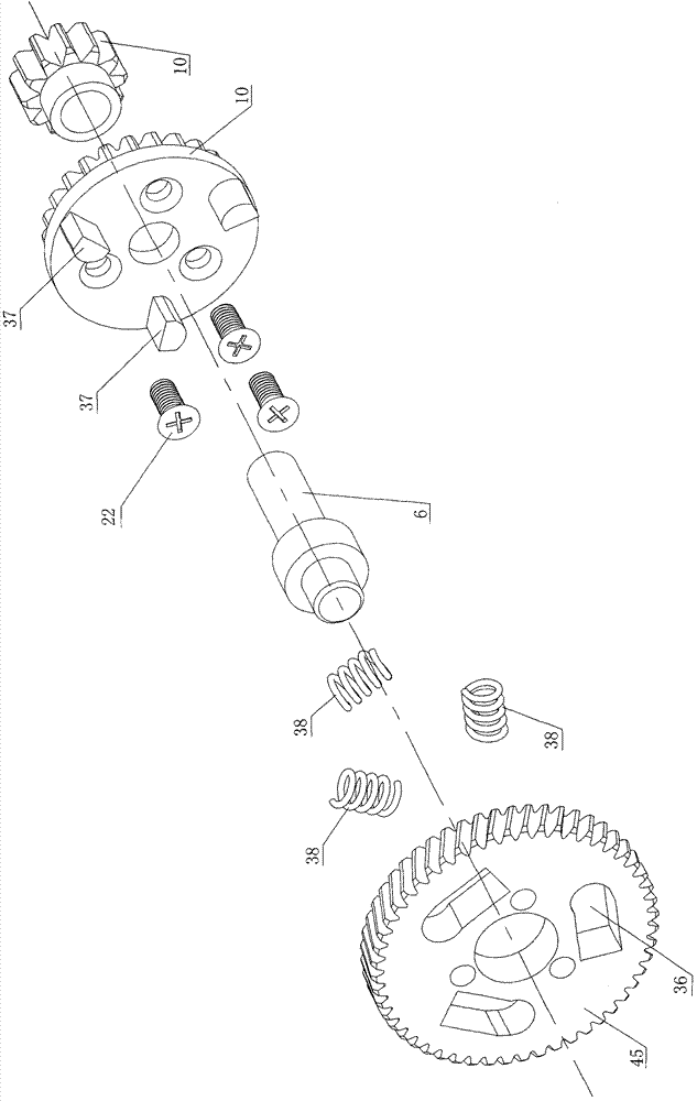
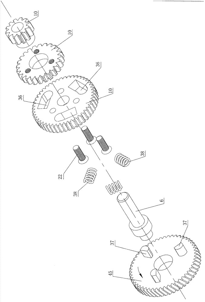
[0018] Such as Figure 1 to Figure 3 As shown, the transmission main shaft with buffer includes the main shaft 6, on which the input teeth 45 are fixed, and the driving gear 10 is idly sleeved on the main shaft 6, and the driving gear 10 can rotate on the main shaft 6 to a limited extent.

[0019] After the motor 3 is energized and rotated, the motor shaft gear 47 rotates to drive the input tooth 45 to rotate, and the input tooth 45 will first rotate the driving gear 10 by a certain angle, so that the shock absorbing spring 38 in the groove 36 is compressed, and then the shock absorbing spring 38 The driving projection 36 makes the driving gear 10 rotate together, and the power is transmitted to the output shaft 5 and the hub ring 1 after the above-mentioned shock absorption and buffering. Thereby achieving the purpose of shock absorption and buffering.

Embodiment 2

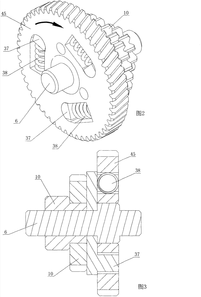
[0021] Such as Figure 4 , Figure 5 As shown in , it differs from Embodiment 1 in that: the input tooth 45 is provided with a bump 37 , and the groove 36 is provided on the driving gear 10 .

[0022] The transmission main shaft with buffer includes a main shaft 6, on which an input tooth 45 is fixed, and the driving gear 10 is vacantly sleeved on the main shaft 6, and the driving gear 10 can rotate on the main shaft 6 to a limited extent.

[0023] After the motor 3 is energized and rotated, the motor shaft gear 47 rotates to drive the input tooth 45 to rotate, and the input tooth 45 will rotate a certain angle to the driving gear 10 first, so that the bump 36 is compressed to the shock-absorbing spring 38 in the groove 36, and then the damping spring 38 is compressed by the damper. The shock spring 38 drives the driving gear 10 to rotate together, and the power is transmitted to the output shaft 5 and the hub ring 1 after the above-mentioned shock absorption and buffering. ...


PUM


Abstract

The invention belongs to the technical field of electric vehicle power transmission, and discloses a transmission spindle with buffer. The transmission spindle solves the problem of an impact due to rigid combination during gear shift in the prior art. The transmission spindle with the buffer comprises a motor, wherein the motor is connected with a box body; a motor shaft, a spindle part and an output shaft are arranged in the box body; and respective self-transmitting gears are arranged on the motor shaft, the spindle part and the output shaft. The transmission spindle is characterized in that input teeth on the spindle part are provided with bumps; the bumps are arranged in grooves in a driving gear; one end of each damping spring pushes against the driving gear; the other end of each damping spring pushes against the bumps of the input teeth; and power of the motor generates the buffer through the mechanism, and then is transferred to the output shaft.

Description

technical field [0001] The invention belongs to the technical field of electric vehicle power transmission. Background technique [0002] The usual electric vehicle motor transmission mechanism is not provided with a buffer mechanism, so that the gears are rigidly combined when shifting gears, resulting in large impact and high noise, which makes the rider feel uncomfortable, and the transmission mechanism is easily damaged. Contents of the invention [0003] In order to solve the above disadvantages, the purpose of the present invention is to provide a simple structure, small size, flexible power output when shifting gears, no impact feeling, more comfortable for the driver, and more durable gear engagement. [0004] In order to realize the purpose of the present invention, the first technical solution of the present invention is: a kind of band buffer transmission main shaft, comprises motor, and motor is connected with casing, is provided with motor shaft, main shaft an...

Claims


Application Information

Patent Timeline
IPC IPC(8): F16H55/14
Inventor 蔡贵席
Owner 蔡旭阳
Why Eureka
Try Eureka