Supercharge Your Innovation With Domain-Expert AI Agents!

A range hood and its control method

A range hood and oil fume technology, applied in the direction of oil fume removal, heating methods, household heating, etc., can solve the problems of large back pressure, loud noise, and large noise increase, and achieve the effect of low noise, noise reduction, and resource utilization

Active Publication Date: 2016-05-25
NINGBO FOTILE KITCHEN WARE CO LTD
View PDF8 Cites 9 Cited by
  • Summary
  • Abstract
  • Description
  • Claims
  • Application Information

AI Technical Summary

Problems solved by technology

[0004] Therefore, the current fan system of the range hood is poor in exhausting the high-resistance pipe network, which greatly affects the adaptability of the range hood and affects the effect of the range hood in the user's state.
At present, when a large part of the range hoods in the city are in use, the lampblack not only needs to pass through its own smoke exhaust pipe, check valve and smoke exhaust channel, but also needs to be connected to a fire prevention device and a public flue to discharge the lampblack. For some residential buildings with higher floors, the public flue is often longer, and the outlet of the public flue is set at the top of the floor, so for the residents on the lower floors, the back pressure of the range hood will be very large, so The use of multi-resistance devices will greatly reduce the flow rate of the range hood when it is in use, the effect of oil suction will be worse, and the noise will be louder. If you want to improve the exhaust effect, most of the current methods are to increase the power of the motor and increase the Exhaust air flow, the result of doing so is often that although the flow rate increases somewhat, the noise will increase greatly.

Method used


Image

  • A range hood and its control method
  • A range hood and its control method
  • A range hood and its control method

Examples


Embodiment Construction

[0024] The present invention will be further described in detail below in conjunction with the accompanying drawings and embodiments.

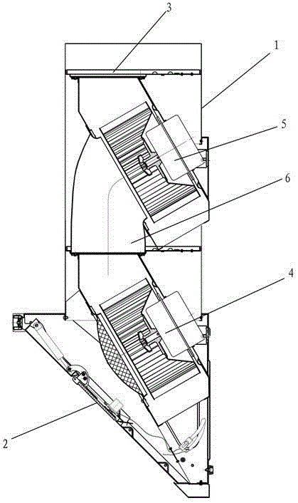
[0025] Such as figure 1 The range hood shown includes a casing 1, a fume inlet 2 is arranged below the casing 1, a fume outlet 3 is arranged above the casing 1, an air inlet is provided in the casing 1 to communicate with the fume inlet 2, and an air outlet is connected to the fume inlet 2. The fan system connected to the oil fume outlet 3, the fan system includes:

[0026] The first centrifugal fan 4, the air inlet of the first centrifugal fan 4 communicates with the oil fume inlet 2;

[0027] The second centrifugal fan 5 , the air inlet of the second centrifugal fan 5 communicates with the outlet of the first centrifugal fan 4 through a curved connecting pipe 6 , and the air outlet of the second centrifugal fan 5 communicates with the oil fume outlet 3 .

[0028] In this embodiment, the first centrifugal fan 4 and the second centrifugal f...


PUM


Abstract

The invention relates to a range hood. The range hood comprises an enclosure, wherein a lampblack inlet is arranged below the enclosure; a lampblack outlet is arranged above the enclosure; the enclosure is internally provided with a fan system; an air inlet of the fan system is communicated with the lampblack inlet; an air outlet of the fan system is communicated with the lampblack outlet. The range hood is characterized in that the fan system comprises a first centrifugal fan and a second centrifugal fan, wherein an air inlet of the first centrifugal fan is communicated with the lampblack inlet; an air inlet of the second centrifugal fan is communicated with an air outlet of the first centrifugal fan through a bent connection pipeline; an air outlet of the second centrifugal fan is communicated with the lampblack outlet. Compared with the prior art, the range hood disclosed by the invention has the advantages that the two matched centrifugal fans are used for increasing air pressure of the fan system so that the fan system can have the greater discharging air pressure even if a high-resistance pipe net exists when the fan system is used; therefore, the discharging flow is also increased. The rotary speeds of the two centrifugal fans do not need to be too high and noises are low; and the requirement of efficient static suction of the range good can be met.

Description

technical field [0001] The invention relates to a range hood and a control method thereof, in particular to a range hood with high efficiency of sucking smoke and low noise. Background technique [0002] The fume absorption effect of a range hood mainly depends on the flow rate it can discharge under the condition of use. The larger the flow rate, the better the fume absorption effect. The discharge flow of the range hood in use depends mainly on the wind pressure of the range hood fan system, the greater the wind pressure, the greater the discharge flow. The wind pressure of the range hood fan system depends on the motor power of the fan system. The greater the motor power, the greater the wind pressure of the fan system. When ordinary household range hoods are in use, the oil fume needs to be discharged through the exhaust pipe, check valve, and exhaust channel. The use of these resistance devices makes the oil fume have a certain back pressure at the oil fume outlet. Pr...

Claims


Application Information

Patent Timeline
Patent Type & Authority Patents(China)
IPC IPC(8): F24C15/20
Inventor 孙佳琪李晓强施旭娜王军元茅忠群诸永定
Owner NINGBO FOTILE KITCHEN WARE CO LTD
Features
  • R&D
  • Intellectual Property
  • Life Sciences
  • Materials
  • Tech Scout
  • Unparalleled Data Quality
  • Higher Quality Content
  • 60% Fewer Hallucinations
Learn More