
Power supply test system used in machine room

A test system and power supply system technology, applied in the field of data center computer room, can solve the problems of increasing test time, time-consuming and labor-intensive, unable to truly reflect battery performance, etc., and achieve the effect of saving time, cost and space

Active Publication Date: 2013-10-23
BEIJING BAIDU NETCOM SCI & TECH CO LTD
View PDF5 Cites 6 Cited by
  • Summary
  • Abstract
  • Description
  • Claims
  • Application Information

AI Technical Summary

Problems solved by technology

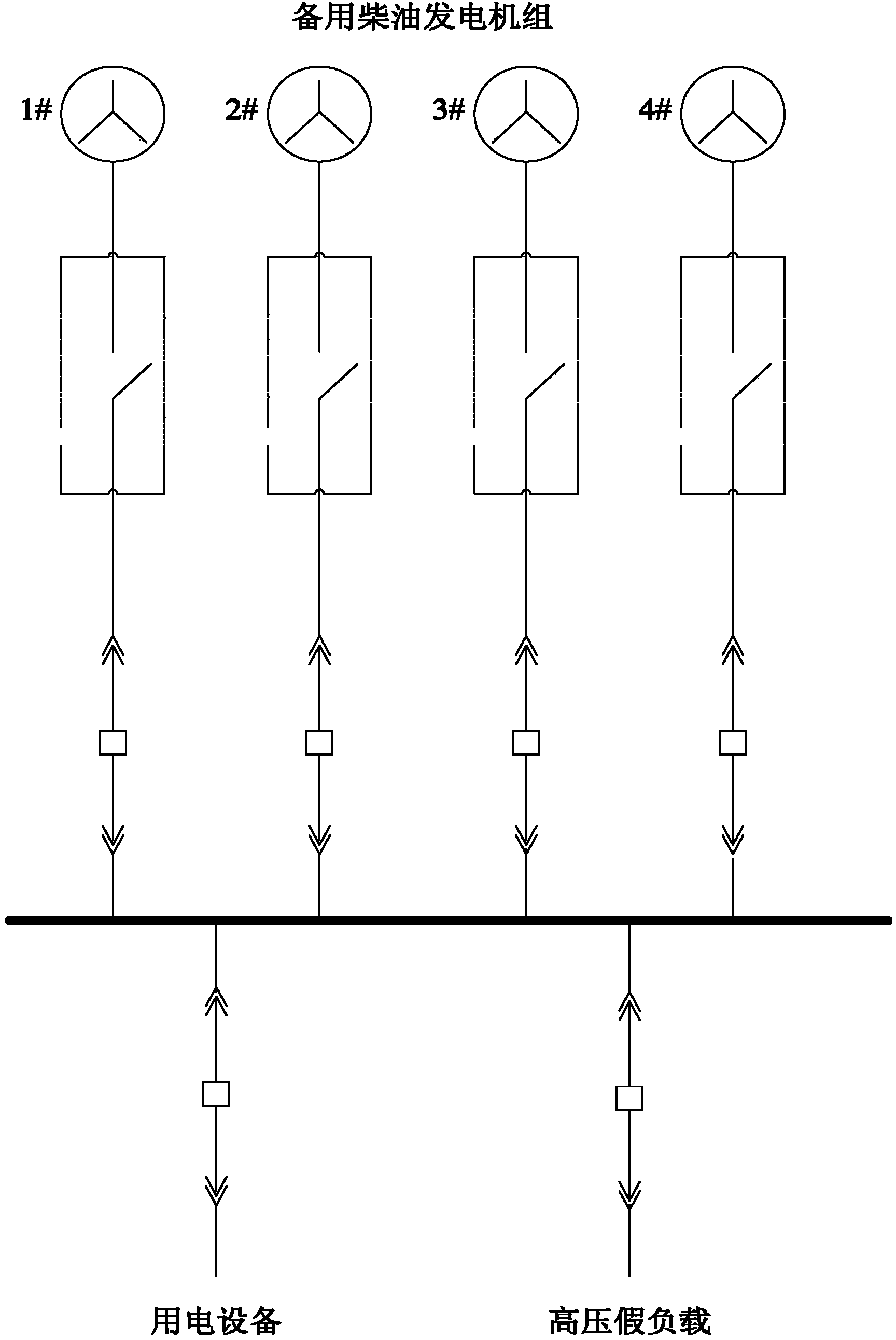
[0004] The disadvantage of the existing technology is that the load characteristics of the 10KV high-voltage dummy load can only be used for 10KV high-voltage generators, so for the low-voltage 220V / 380V power supply system in the machine room, it is necessary to rent a low-voltage dummy load for testing, which increases the cost
And because the rented low-voltage dummy load is not fixedly connected, it is time-consuming and labor-intensive to find the location of the dummy load and connect a large number of cables for each test.
After the computer room is enabled, the IT equipment is used to test the power supply system directly. There are two problems in this way. First, the real IT equipment is used for testing. There is a greater risk due to the uncertainty of the battery in the power supply system under test. Secondly, due to the actual The load of IT equipment changes frequently and there is a big gap with the calculation load, which causes the discharge current of the battery to be different each time and is much smaller than the calculation current, which cannot truly reflect the performance of the battery, and the battery discharge time will also vary accordingly. Greatly improved, increased testing time, and increased the work intensity of maintenance personnel

Method used


Image

  • Power supply test system used in machine room
  • Power supply test system used in machine room
  • Power supply test system used in machine room

Examples


Embodiment Construction

[0030] Embodiments of the present invention are described in detail below, examples of which are shown in the drawings, wherein the same or similar reference numerals designate the same or similar elements or elements having the same or similar functions throughout. The embodiments described below by referring to the figures are exemplary only for explaining the present invention and should not be construed as limiting the present invention.

[0031]The following disclosure provides many different embodiments or examples for implementing different structures of the present invention. To simplify the disclosure of the present invention, components and arrangements of specific examples are described below. Of course, they are only examples and are not intended to limit the invention. Furthermore, the present invention may repeat reference numerals and / or letters in different instances. This repetition is for the purpose of simplicity and clarity and does not in itself indicate...


PUM


Abstract

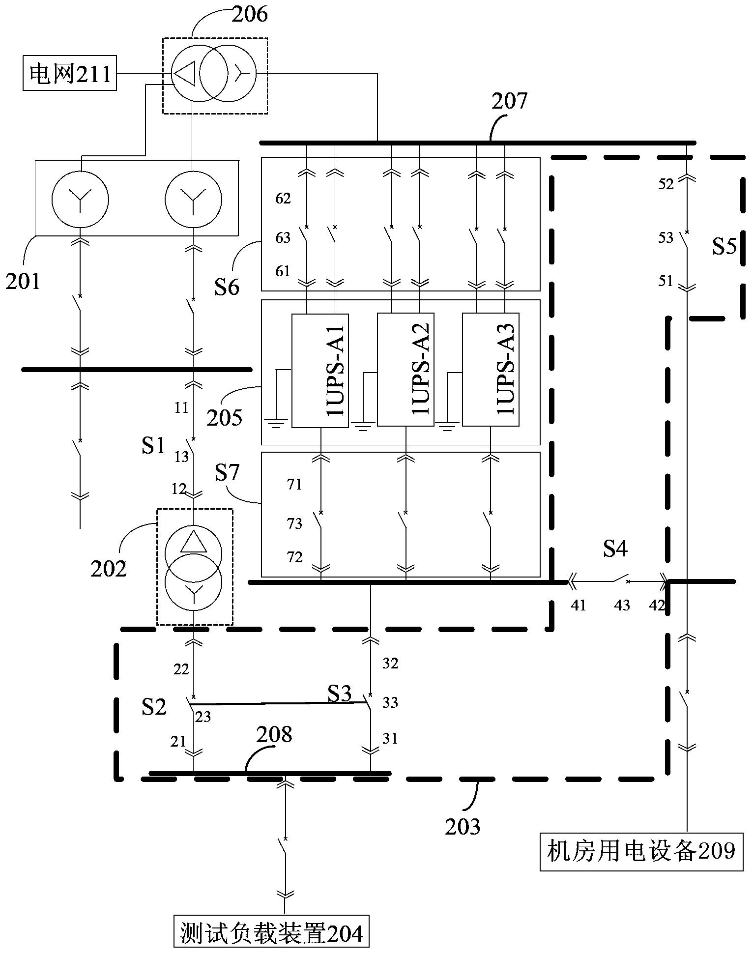
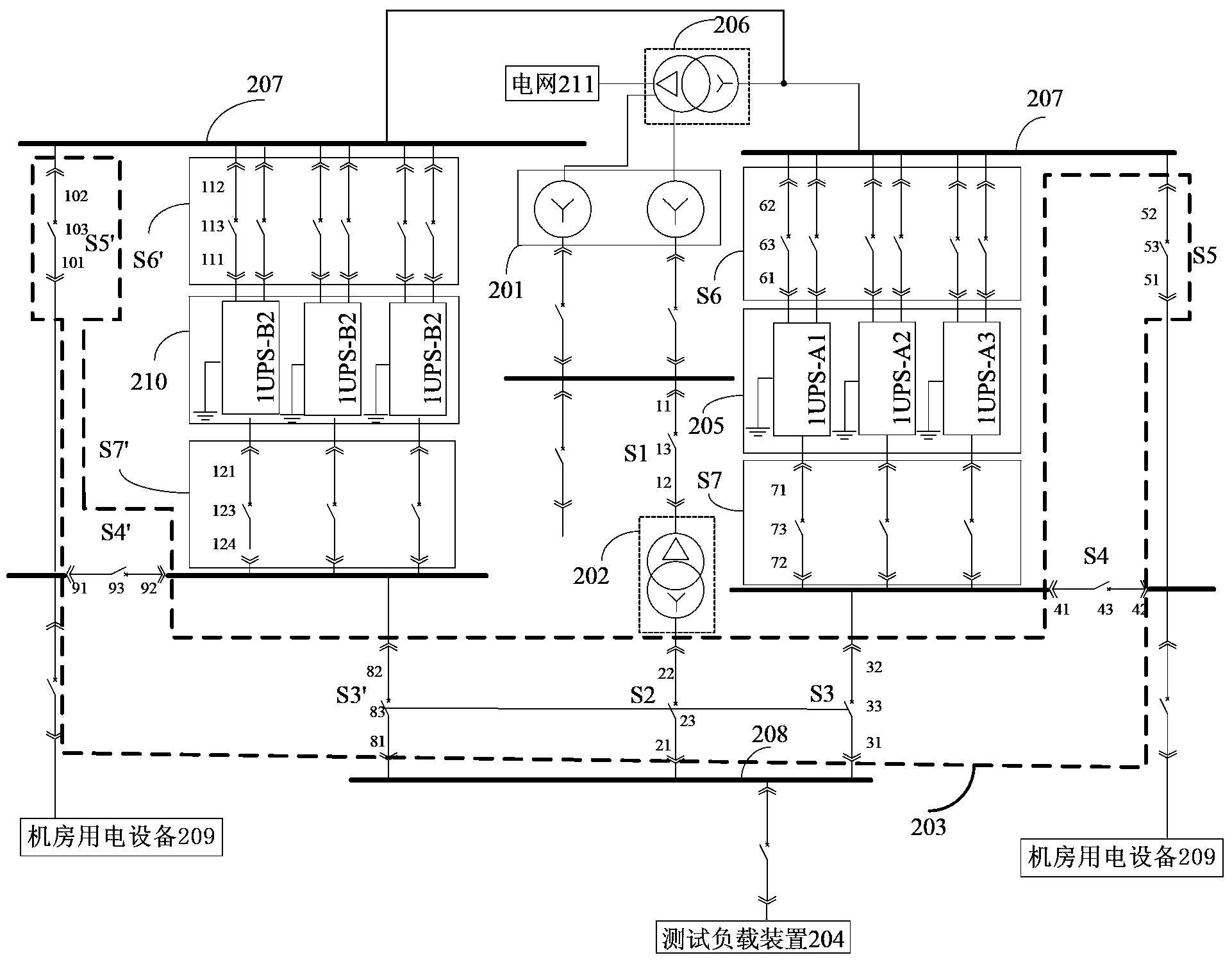
The invention discloses a power supply test system used in a machine room. The power supply test system comprises an electric generator, a first transformer, a selecting device, a test loading device, a power supply bus, a first UPS (Uninterruptable Power System) power supply device and a control device, wherein the primary side of the first transformer is connected with the electric generator, and the first transformer is used for performing voltage transformation on alternating current output by the electric generator; the selecting device is respectively connected with the secondary side of the first transformer and electric equipment for the machine room; the test loading device is connected with the selecting device; the power supply bus is connected with the selecting device; the first UPS power supply device is respectively connected with the power supply bus and the selecting device; and the control device is connected with the selecting device and the test loading device, and is used for controlling the selecting device and the test loading device so as to test a power supply system of the machine room. With only a suit of test loading device, the system can test the power supply system of the machine room before and after starting, so that the cost and space are reduced, cables do not need to be connected during testing, and the power supply test system is simple, quick, safe and reliable.

Description

technical field [0001] The invention relates to the technical field of a data center computer room, in particular to a power supply test system for a computer room. Background technique [0002] In order to ensure the quality and performance delivered by the data center computer room, many newly-built computer rooms will use dummy loads to simulate the power consumption of real equipment to comprehensively test the performance of the power supply system of the entire computer room. This process is a comprehensive test. Many electromechanical equipment in the data center computer room also need to be operated under load for regular maintenance, such as UPS (Uninterruptible Power Supply, uninterruptible power supply) batteries and generators, etc. Use real loads to test and maintain the power supply system in the computer room. However, with the continuous increase in the scale of the data center computer room and the continuous improvement of reliability requirements, the wo...

Claims


Application Information

Patent Timeline
IPC IPC(8): G01R31/00G01R31/34G01R31/40
Inventor 张企宇
Owner BEIJING BAIDU NETCOM SCI & TECH CO LTD
Learn More