Planar optical element and design method thereof

A technology of optical components, planes, applied in the field of optics, which can solve problems such as limitations

Inactive Publication Date: 2013-10-23
CAPITAL NORMAL UNIVERSITY
View PDF6 Cites 17 Cited by
  • Summary
  • Abstract
  • Description
  • Claims
  • Application Information

AI Technical Summary

Problems solved by technology

[0004] At present, the application of phase discontinuity to beam shaping is still very limited, especially in the design of optical components, which needs further research

Method used


Image

  • Planar optical element and design method thereof
  • Planar optical element and design method thereof
  • Planar optical element and design method thereof

Examples


Embodiment Construction

[0021] The technical solutions of the present invention will be described in further detail below with reference to the accompanying drawings and embodiments.

[0022] The embodiments of the present invention design a planar diffractive optical element with antenna micro-arrays with a specific structure, so as to realize an ideal beam shaping effect.

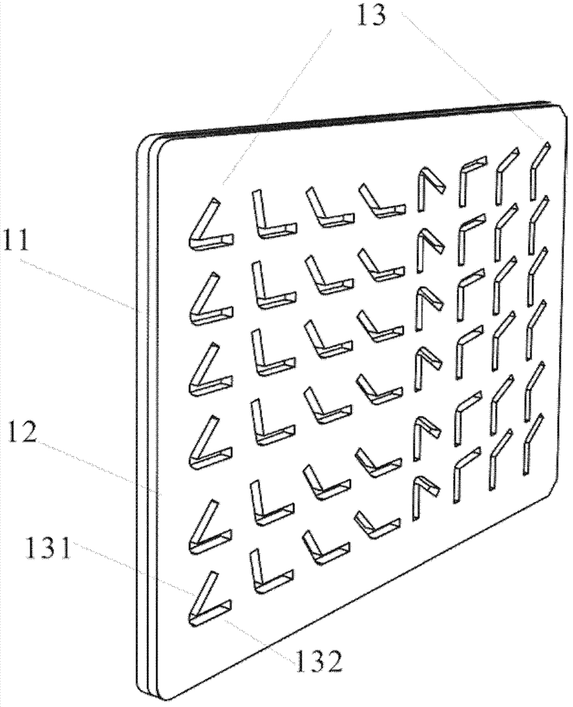
[0023] figure 1 It is a partial structural schematic diagram of the planar optical element of the embodiment of the present invention. The planar optical element can be used to realize the beam shaping effect of full-wavelength spherical lenses, spherical mirrors, cylindrical lenses, cylindrical mirrors and other types of optical elements. As shown in the figure, the planar optical element includes: a substrate 11 and a metal film 12 . The material of the substrate 11 is a material with high transmittance for the used light band, and the thickness ranges from 300 μm to 1000 μm. The metal film 12 can be a good conductor, such ...


PUM


Abstract

A planar optical element and a design method thereof. The design method of the planar optical element comprises: designing a group of structures having a determined discrete phase; designing a two-dimensional antenna microarray (13) by using the group of structures having the determined discrete phase as array elements; and a basement (11) and a metal film (12) having a structure of the two-dimensional antenna microarray (13) forming the planar optical element. In the method, the amplitude and phase of a radiation field that has a vertical polarization state and is excited when a beam with a specific wavelength and a polarization state is incident on the planar optical element are modulated by modulating a structure parameter of the antenna array element, thereby shaping the beam as expected, and obtaining a desirable beam shaping result.

Description

technical field [0001] The invention relates to the field of optics, in particular to a planar optical element and a design method thereof. Background technique [0002] Traditional optical devices rely on the phase shift gradually accumulated during light propagation to achieve beam shaping. A new degree of freedom for beam shaping can be obtained by introducing a phase mutation within a certain wavelength range. The sudden change of phase can be achieved by properly designing the interface of two different media. This phase discontinuity in light propagation can be studied when the beam propagates across the interface of an optical resonant array with spatially varying phase response and subwavelength spacing. By designing a suitable optical resonator model, the condition of equal amplitude of the beam along the interface and a constant phase gradient can be obtained. In an optical resonator, the phase shift between outgoing and incident light varies appropriately acros...

Claims


Application Information

Patent Timeline
Patent Type & Authority Applications(China)
IPC IPC(8): G02B27/09G02B27/00
CPCG02F1/29G02B5/00G02B5/3083H01Q15/0013H01Q15/006G02F2203/18G06F30/00
Inventor 张岩胡丹
Owner CAPITAL NORMAL UNIVERSITY
Why Eureka
Try Eureka