Control method based on gravity compensator

A technology of gravity compensation and control method, which is applied in the direction of photolithography exposure device, microlithography exposure equipment, etc., and can solve the problem that the gas path is difficult to adjust and balance

Active Publication Date: 2013-10-23
SHANGHAI MICRO ELECTRONICS EQUIP (GRP) CO LTD
View PDF6 Cites 2 Cited by
  • Summary
  • Abstract
  • Description
  • Claims
  • Application Information

AI Technical Summary

Problems solved by technology

Its disadvantage is that when the object is tilte...

Method used


Image

  • Control method based on gravity compensator
  • Control method based on gravity compensator
  • Control method based on gravity compensator

Examples


Embodiment Construction

[0042] Specific embodiments of the present invention will be described in detail below in conjunction with the accompanying drawings.

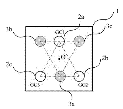
[0043] The invention provides a vertical control method based on a gravity compensator, which can balance the gravity of an object and provide the driving force for the vertical movement of the object in the directions of Z, Rx, and Ry. The gravity compensator is connected with the vertical motor loop Parallel connection, the gravity compensator includes three independent air circuits, the gravity compensator and the vertical motor share three vertical logic axes, the signal is divided into two paths after passing through the logic axes, one path controls the vertical motor, and the other path controls The gravity compensator.

[0044] figure 1 It is a schematic layout diagram of the gravity compensator of the first embodiment of the present invention. Such as figure 1As shown in , the gravity compensator adopts a common air-floating stru...


PUM


Abstract

The invention discloses a vertical control policy and parameter calibration method based on a gravity compensator. The gravity compensator can balance an object gravity and provides a driving force of vertical movement of an object in Z, Rx and Ry directions; the gravity compensator is connected with a vertical motor loop in parallel; the gravity compensator comprises three independent gas paths; the gravity compensator and the vertical motor commonly use three logic shafts in the vertical direction; signals are divided into two paths after passing through the logic shafts; one path controls the vertical motor; and the other path controls the gravity compensator.

Description

technical field [0001] The invention relates to precision motion equipment, in particular to a control method based on a gravity compensator. Background technique [0002] In precision sports equipment, the gravity of the object has a great influence on the vertical movement, and measures need to be taken to compensate. In lithography machines in recent years, the combination of gravity compensator and vertical motor is widely used. Gravity compensator (GC for short) is specially used to balance the gravity of the driving object. The most common one is gas drive, and some are driven by magnetic suspension or spring. , while the vertical motor is responsible for driving the vertical movement of the object for decoupling control. [0003] For the detailed introduction of the gravity compensator in the prior art, please refer to US6337484. As shown in the patent US6337484, this technical solution controls the horizontal and vertical movements of the micro-motion table separat...

Claims


Application Information

Patent Timeline
IPC IPC(8): G03F7/20
Inventor 赵辉廖飞红段立峰
Owner SHANGHAI MICRO ELECTRONICS EQUIP (GRP) CO LTD
Why Eureka
Try Eureka