
Bearing cavity ventilation design method of aero-engine

An aero-engine and design method technology, applied in calculation, special data processing applications, instruments, etc., can solve the problem of calculation, control of engine lubrication system, design and verification of main bearing cavity seal, and failure to obtain engine shaft seal. Questions such as

Active Publication Date: 2013-10-23
AECC SHENYANG ENGINE RES INST
View PDF4 Cites 14 Cited by
  • Summary
  • Abstract
  • Description
  • Claims
  • Application Information

AI Technical Summary

Problems solved by technology

[0005] Therefore, the bearing cavity pressure of the throttling and ventilated engine lubrication system cannot be obtained by calculation at the beginning of the design. The ground state point data can only be obtained through the ground test run, and any state point data of the high-altitude state cannot be obtained through test run or calculation.
It is also impossible to obtain important data such as whether the seal of the main shaft of the engine is reversed within the flight envelope, which seriously restricts the design and verification of the engine lubrication system and the seal of the main bearing cavity

Method used


Image

  • Bearing cavity ventilation design method of aero-engine
  • Bearing cavity ventilation design method of aero-engine
  • Bearing cavity ventilation design method of aero-engine

Examples


Embodiment 1

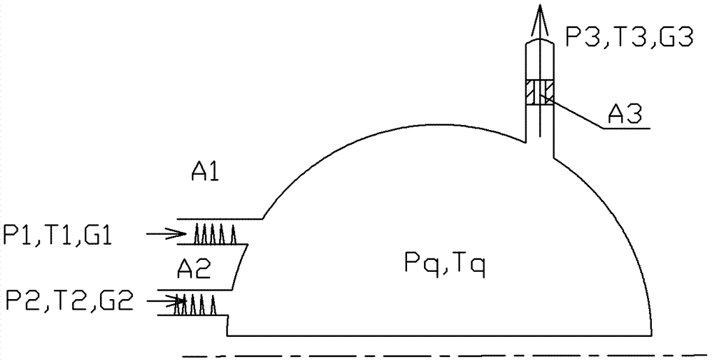
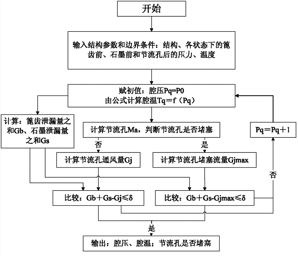
[0093] The invention provides a ventilation design method for an aero-engine bearing cavity, which is characterized in that: the aero-engine bearing cavity ventilation design method involves the basic assumption of throttling ventilation aero-engine bearing cavity, the calculation of the pressure and flow of the throttle hole Method, cavity pressure calculation process.

[0094] Firstly, the boundary parameters of the bearing cavity are obtained. The calculation of the bearing cavity pressure is obtained through multiple iterative joint calculations of the air system and the accessory casing cavity pressure. In each state of the engine corresponding to the flight altitude, calculate the pressure, temperature, and flow rate before sealing of the air system, and use the local atmospheric pressure, high-altitude valve, centrifugal ventilator, etc. to reverse the cavity pressure and cavity temperature of the accessory casing, respectively as the bearing Boundary parameters for cav...


PUM


Abstract

The invention relates to a bearing cavity ventilating design method of an aero-engine and fundamental assumption of throttling and ventilating bearing cavity of the aero-engine, a method for calculating pressure and flow of a throttling hole, and a cavity pressure calculating procedure. Firstly, boundary parameters of the bearing cavity are obtained and repeated iteration united algorithm is performed on cavity pressure of an air system and an accessory cartridge receiver to obtain the pressure of the bearing cavity. Secondly, assumption is performed as follows. Only steady-state conditions of the aero-engine undergo calculation. The total pressure of the bearing cavity in a steady sate is assumed to stagnation pressure. A flowing process of air currents passing through the throttling hole from the bearing cavity is assumed to be an isoenergetic isentropic process. An oil returning pump of the bearing cavity neglects influences on the cavity pressure and then the throttling and ventilating bearing cavity of the aero-engine is solved. The bearing cavity ventilating design method of the aero-engine has the advantages that calculating data on the pressure of the bearing cavity of a throttling and ventilating aero-engine lubricating system can be obtained in a flight envelope and design of throttling and ventilating systems of lubricating systems of power of a military aero-engine, a civil plane, a gas turbine and a boat can be guided and the application prospect is wide.

Description

technical field [0001] The invention relates to the field of lubricating system design of an aero-engine, in particular to a method for designing the ventilation of an aero-engine bearing chamber. Background technique [0002] Aeroengine lubrication system consists of oil supply system, oil return system and ventilation system. Among them, the ventilation system includes the main shaft sealing device, ventilation pipeline, centrifugal ventilator, high-altitude valve, etc. The design goal of the ventilation system is to ensure that the bearing cavity pressure in the engine flight envelope is stable within a certain range. With the increasing flight altitude required by aircraft to complete tasks, the throttling ventilation structure of the aero-engine lubrication system ventilation system has been widely used in engine design. Throttle ventilation is the most common ventilation method for the bearing cavity of the engine with grate tooth seal structure. Its purpose is that w...

Claims


Application Information

Patent Timeline
IPC IPC(8): G06F19/00
Inventor 郁丽李国权
Owner AECC SHENYANG ENGINE RES INST
Learn More