
Digital-to-analog convertor

A digital-to-analog converter technology, applied in the field of digital-to-analog converters, can solve problems such as monotony

Inactive Publication Date: 2013-10-23
SUZHOU BATELAB MICROELECTRONICS
View PDF2 Cites 3 Cited by
  • Summary
  • Abstract
  • Description
  • Claims
  • Application Information

AI Technical Summary

Problems solved by technology

However, it is precisely these devices that need to provide accurate, monotonic digital-to-analog conversion

Method used


Image

  • Digital-to-analog convertor
  • Digital-to-analog convertor
  • Digital-to-analog convertor

Examples


Embodiment Construction

[0022] A typical example of a conventional N-bit DAC providing a guaranteed monotonic conversion is shown in simplified schematic form in figure 1 explained in. DAC100 consists of a set of 2 N node connected resistive element 101 with a set of 2 N A switching device 102 is coupled to the input of a unity gain buffer 109 , directly to element 103 and through element 108 . Although a specific instance of buffer 109 is illustrated, any conventional buffer may be used. Current source 107 in buffer 109 drives the sources of PMOS transistors 103 and 104 . The drains of transistors 103 and 104 are coupled to the drains of NMOS transistors 105 and 106 . Transistors 105 and 106 form a current mirror. The high-gain inverting amplifier 108 provides negative feedback through the drain of the transistor 103 and the gate of the transistor 104 . This feedback ensures that the drain currents of transistors 105 and 106 are substantially equal. In turn, this ensures that the gate voltage...


PUM


Abstract

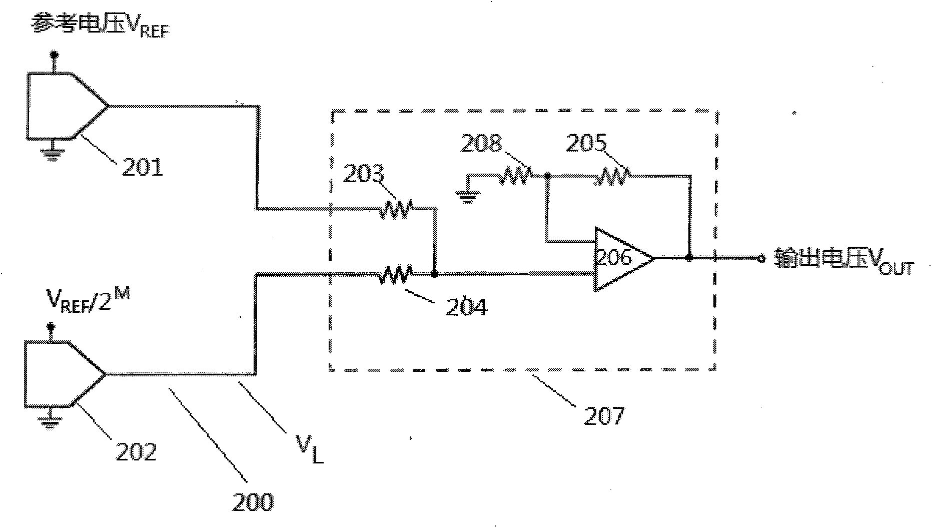
The invention discloses a digital-to-analog convertor (DAC) which is characterized in that the output end of a sub-word pair in a DAC circuit is obtained through modulating the bias voltage of a differential buffer amplifier and calculating the sum. The invention also provides embodiments of different alternative DACs, wherein the input stage of one operational amplifier responds to the modulation of the offset voltage of one digital signal differential buffer amplifier, and linear and monotonicity errors caused by inaccurate components are eliminated by using an interpolation technology.

Description

technical field [0001] The present invention relates to digital to analog converters. More specifically, it has, on the one hand, an improved architecture of the segmented digital-to-analog converter and, on the other hand, provides digital-to-analog conversion in which an analog output voltage is related to a digital input word of a certain monotonic function. Background technique [0002] A digital-to-analog converter (DAC) has a segmented architecture, and its typical operation is to control the DAC circuit by dividing a digital input word into sub-words of different parts. For example, a digital input word can be divided into a more significant (i.e. MS) subword and a less important (i.e. LS) subword, then the MS subword is used to generate a first intermediate current or voltage signal , with the second intermediate current or summed to generate a voltage signal responsive to the LS subword. This segmented structure can be particularly effective in reducing the number...

Claims


Application Information

Patent Timeline
IPC IPC(8): H03M1/66
Inventor 李真
Owner SUZHOU BATELAB MICROELECTRONICS
Learn More