
Wireless humiture sensor network structure based on zigbee

A temperature and humidity sensor, humidity sensor technology, applied in wireless communication, network topology, electrical components, etc., can solve problems such as short circuit, unsafe operation of equipment in the cabinet, equipment damage, etc.

Inactive Publication Date: 2013-10-23
上海宽岱电讯科技发展有限公司
View PDF5 Cites 8 Cited by
  • Summary
  • Abstract
  • Description
  • Claims
  • Application Information

AI Technical Summary

Problems solved by technology

[0003] Although, nowadays, the computer room is equipped with camera monitoring to ensure the security of the computer room, but there is no security guarantee for the operation status of the equipment in the cabinet.
Especially if the temperature overheating causes equipment damage or short circuit, it cannot be known in time, which will bring huge losses to both the website company and the operator

Method used


Image

  • Wireless humiture sensor network structure based on zigbee
  • Wireless humiture sensor network structure based on zigbee
  • Wireless humiture sensor network structure based on zigbee

Examples


Embodiment Construction

[0038] The specific implementation manners of the present invention will be described in detail below in conjunction with the accompanying drawings of the embodiments.

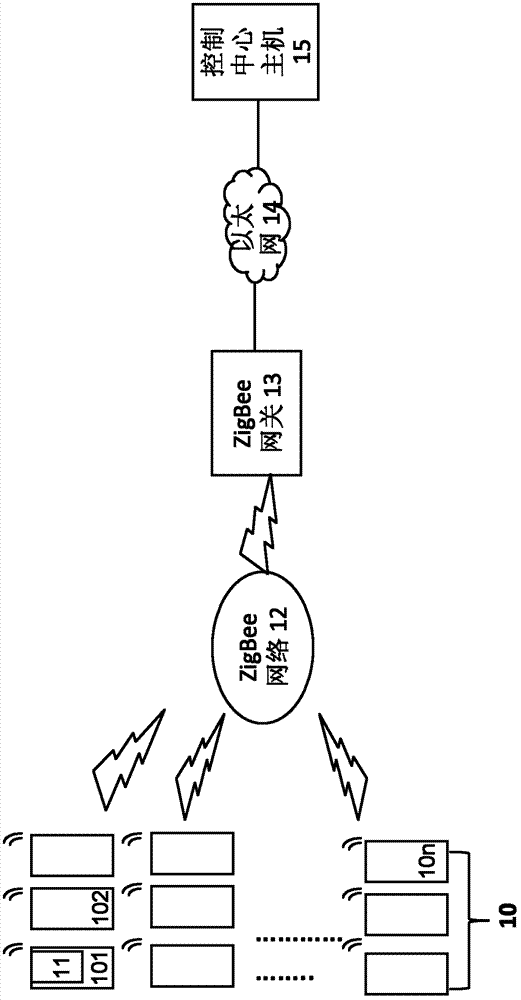
[0039] see figure 1 , figure 1 It is a schematic diagram of the wireless temperature and humidity sensor network structure based on zigbee of the present invention, and the network structure includes the following four components:

[0040] (1) Computer room 10

[0041] Several cabinets 101, 102, . . . , 10n with communication equipment are arranged in the machine room 10 .

[0042] (2) Several wireless temperature and humidity sensors 11

[0043] Several wireless temperature and humidity sensors 11 are distributed in each cabinet 101, 102, ..., 10n, and the structure of each wireless temperature and humidity sensor 11 can be found in image 3 , which contains:

[0044] The temperature and humidity sensor 111 collects the temperature and humidity signal in the cabinet, and the present embodiment adopts the...


PUM


Abstract

The invention provides a wireless humiture sensor network structure based on a zigbee, relates to the wireless humiture sensor technology, and solves the problem that the security of running devices in a cabinet of a machine room is not guaranteed. The structure comprises a plurality of wireless humiture sensors based on the zigbee which are distributed in each cabinet of the machine room, a ZigBee wireless gateway, and a control center host. The wireless humiture sensors collect a humiture signal in the cabinet, preprocess the signal into humiture data in a ZigBee protocol format, and transmit the humiture data; the ZigBee wireless gateway receives, through a ZigBee network, the humiture data in the ZigBee protocol format transmitted by the wireless humiture sensors, and transforms the humiture data in the ZigBee protocol format into the humiture data in an Ethernet protocol format; and the control center host, through an Ethernet telecommunication transmission, receives the humiture data in the Ethernet protocol format transmitted by the ZigBee gateway, and displays the humiture data in a real time manner. The sensor network structure can display the humiture in the cabinet in the control center host in the real time manner, so as to ensure the safe operation of devices in the cabinet.

Description

technical field [0001] The invention relates to wireless temperature and humidity sensor technology, in particular to a zigbee-based wireless temperature and humidity sensor network structure. Background technique [0002] With the rapid development of the Internet, many websites have sprung up. For cost and security considerations, many website companies prefer to put their website servers in the operator's computer room, which is collectively referred to as IDC computer room. This puts forward higher security requirements for the cabinets where servers and other equipment are placed in the operator's computer room. [0003] Although the computer room is equipped with camera monitoring to ensure the safety of the computer room, the operation status of the equipment in the cabinet cannot be guaranteed. Especially if overheating causes equipment damage or short circuit, if we cannot know in time, it will bring huge losses to both the website company and the operator. Theref...

Claims


Application Information

Patent Timeline
IPC IPC(8): H04W84/18
Inventor 司昊杰
Owner 上海宽岱电讯科技发展有限公司
Learn More