LED illumination control system and control method thereof

A technology of LED lighting and control system, which is applied in the direction of lighting devices, light sources, electric light sources, etc., can solve problems such as inability to use, and achieve the effects of reducing heat generation, prolonging life, and using and maintaining safety

Inactive Publication Date: 2013-10-23
金德奎
View PDF6 Cites 4 Cited by
  • Summary
  • Abstract
  • Description
  • Claims
  • Application Information

AI Technical Summary

Problems solved by technology

[0003] The technical problem to be solved by the present invention is to provide an LED lighting control system and its control method, which solves the problem that the existing LED lighting control system needs to use two lines of power supply and signal to realize the division of the main controller into the sub-controller and the sub-controller. The power

Method used


Image

  • LED illumination control system and control method thereof
  • LED illumination control system and control method thereof
  • LED illumination control system and control method thereof

Examples


Example Embodiment

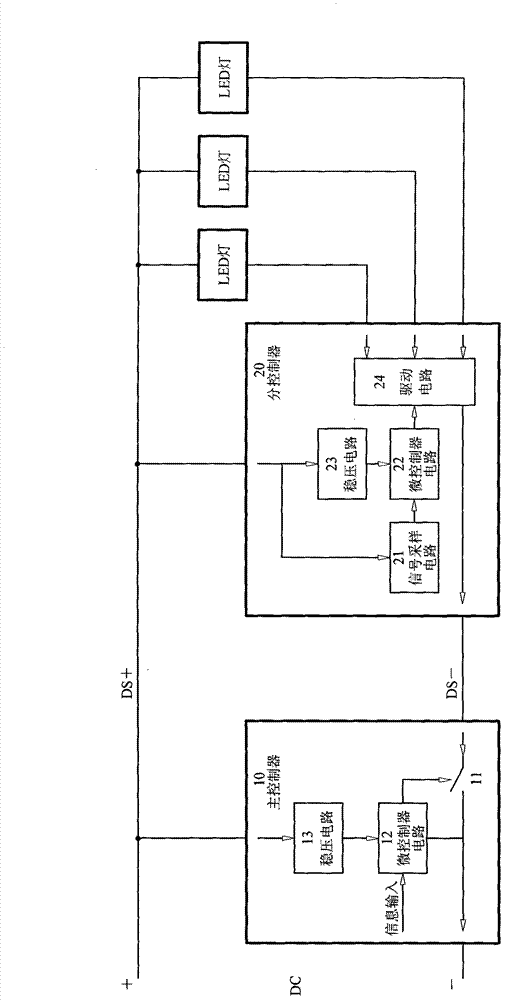
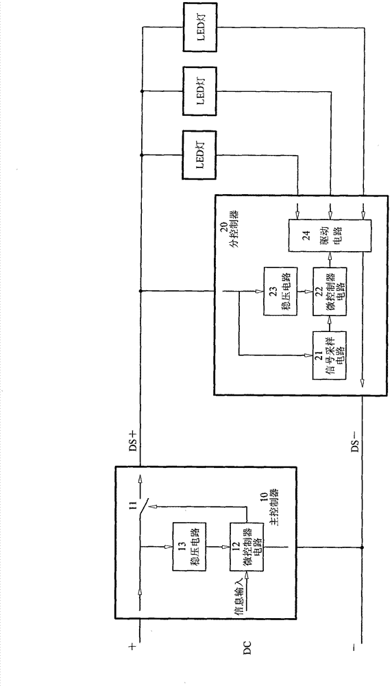
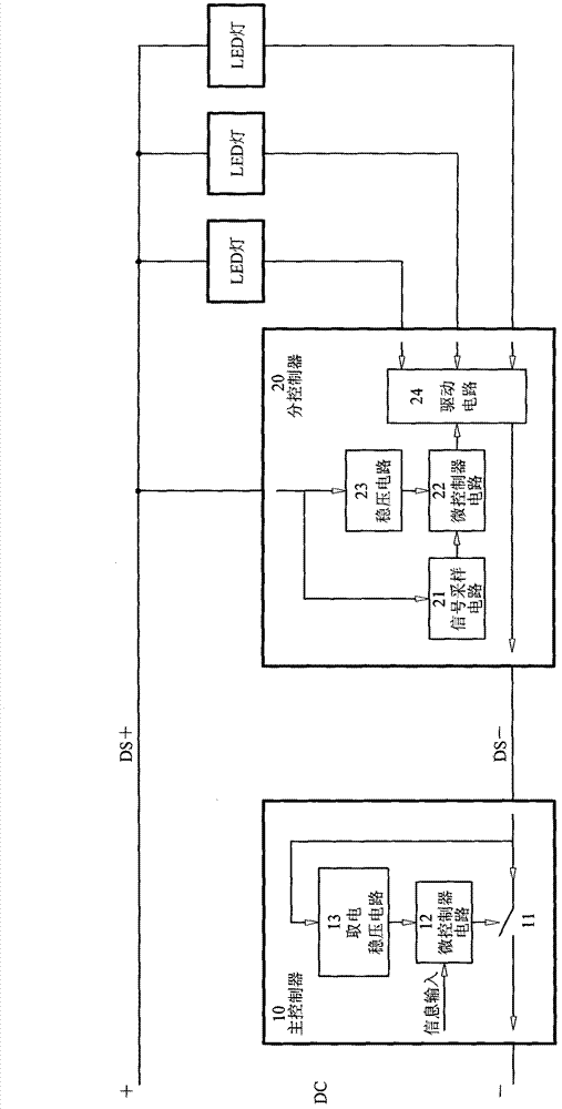
[0062] The present invention will be further described below in conjunction with the drawings and embodiments.

[0063] The first embodiment of the present invention figure 1 As shown, an LED lighting control system of the present invention includes a main controller 10 and a sub-controller 20. The main controller 10 includes a switch tube 11 and a microcontroller circuit 12; the sub-controller 20 includes a signal sampling circuit 21, a micro The controller circuit 22, the voltage stabilizing circuit 23, and the driving circuit 24; the output end of the switch tube 11 of the main controller 10 is connected in series between the DC negative pole to the DC power supply and control line DS- of the sub-controller 20, and its control end is connected with The signal output terminal of the microcontroller circuit 12 of the main controller 10 is connected.

[0064] The power input end of the voltage stabilizing circuit 23 of the sub-controller 20 is connected to the DC power supply and c...


PUM


Abstract

The invention relates to an LED illumination control system including a master controller and a sub-controller. The master controller includes a switch tube and a micro-controller circuit. The sub-controller includes a signal sampling circuit, a micro-controller circuit, a voltage-stabilizing circuit and a driving circuit. An output end of the switch tube of the master controller is connected serially between direct-current electricity transmission and signal lines through which direct current is transmitted to the sub-controller. A control end of the switch tube of the master controller is connected with a signal-output end of the micro-controller circuit of the master controller. A signal-input end of the signal-sampling circuit of the sub-controller is connected with a power input end of the voltage stabilizing circuit and the direct-current electricity transmission and signal lines and a signal-output end of the signal-sampling circuit of the sub-controller is connected with a signal-input end of the micro-controller circuit. The signal-output end of the micro-controller circuit is connected with a signal-input end of the driving circuit. A control output end of the driving circuit is connected with a load. The other end of the load is connected with the direct-current electricity transmission and signal lines. Through use of the two direct-current electricity transmission and signal lines, the LED illumination control system enables power supply and control of the sub-controller and the load of the sub-controller by the master controller to be realized and a problem, which exists in the prior art, that the LED illumination control system cannot be used directly on a two-wire illuminating line which is already well laid is solved.

Description

technical field [0001] The invention relates to a control system and a control method thereof, in particular to an LED lighting control system and a control method thereof. Background technique [0002] The existing LED lighting control system usually uses two lines of power supply and signal connection between the main controller and each sub-controller to control multiple and multiple groups of LED lights. The power supply and signal terminals of each sub-controller are connected to the power supply Lines and signal lines are connected, power and signals go through separate channels, and signal communication usually uses RS485 or DMX512. Since two different lines are required to transmit power and control signals respectively, the wiring costs are high and labor-intensive, and it is impossible to use the existing lines to realize the main controller to multiple sub-controllers and the many LED lights carried by these sub-controllers. control. Some systems that use DMX512...

Claims


Application Information

Patent Timeline
IPC IPC(8): H05B37/02
Inventor 金德奎
Owner 金德奎
Why Eureka
Try Eureka