Bio-electricity signal detection circuit, lead wire detection circuit and medical device
A detection circuit and lead wire technology, which is applied in the direction of bioelectrical signal measurement, voltage-only measurement, and components of electrical measuring instruments, etc. Problems such as design difficulty and cost, to achieve the effect of simple circuit structure
- Summary
- Abstract
- Description
- Claims
- Application Information
AI Technical Summary
Problems solved by technology
Method used
Image

Examples
Embodiment 1
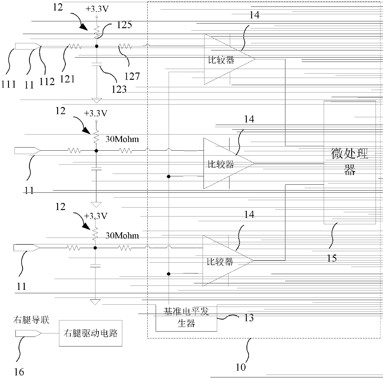
[0026] Please refer to figure 1 , a bioelectrical signal detection circuit, including a lead wire 11 for normal testing, a bias circuit 12 and a lead wire detection circuit 10, and the lead wire detection circuit 10 includes a reference level generator 13, a comparator 14 and a control logic module , the control logic module is used to realize the logic judgment function, which can be realized by devices such as LogicGates (logic gate), MCU (microcontroller), and FPGA (field programmable gate array). In this embodiment, the control logic module includes the microprocessor 15 as an example for illustration.
[0027] The lead wire 11 includes a contact end 111 and a signal output end 112 for contacting the human body. When collecting human tissue signals, the contact end 111 is clamped or pasted into contact with the human body, and the human biological body collected through the lead wire 11 The electrical signal is output through the signal output terminal 112 . The bias cir...
Embodiment 2
[0043] Such as Figure 4 As shown, the difference between this embodiment and Embodiment 1 lies in the sharing of comparators. The bioelectrical signal detection circuit includes a lead wire 21, a bias circuit 22 and a lead detection circuit 20, and the lead detection circuit includes a reference level generator 23, a comparator 24, a microprocessor 25 and a multi-way switch 27. The setting circuit 22 forms a loop through the lead wire 21 and the reference lead wire 26, and the signal output end of each lead wire 21 is connected to one of the multiple input terminals of the multi-way switch 27, and the output end of the multi-way switch 27 is connected to To one of the two input terminals of the comparator 24, the multi-way switch 27 polls the signal output terminals of each lead wire, and the other input terminal of the comparator 24 is connected with the reference level generator 23, and accesses the reference voltage The output end of the comparator 24 is connected to the ...
PUM
 Abstract
Description
Claims
Application Information
 - R&D Engineer
- R&D Manager
- IP Professional
- Industry Leading Data Capabilities
- Powerful AI technology
- Patent DNA Extraction
Browse by: Latest US Patents, China's latest patents, Technical Efficacy Thesaurus, Application Domain, Technology Topic.
© 2024 PatSnap. All rights reserved.Legal|Privacy policy|Modern Slavery Act Transparency Statement|Sitemap