Electromagnetic relays and switching devices

A technology for electromagnetic relays and switching devices, applied in electromagnetic relays, detailed information of electromagnetic relays, relays, etc., can solve the problems of troublesome implementation, difficult modification and high cost, and achieve the effect of reducing ampere force, avoiding large-scale modification and maintaining safety.

Active Publication Date: 2016-01-13
TYCO ELECTRONICS SHENZHEN
View PDF7 Cites 0 Cited by
  • Summary
  • Abstract
  • Description
  • Claims
  • Application Information

AI Technical Summary

Problems solved by technology

In the case of increasing the rated current, if the electromagnetic relay is redesigned, its modification is difficult, the cost is high, and the implementation is troublesome.

Method used


Image

  • Electromagnetic relays and switching devices
  • Electromagnetic relays and switching devices
  • Electromagnetic relays and switching devices

Examples


Embodiment Construction

[0056] The present invention is described in detail below in conjunction with accompanying drawing and embodiment:

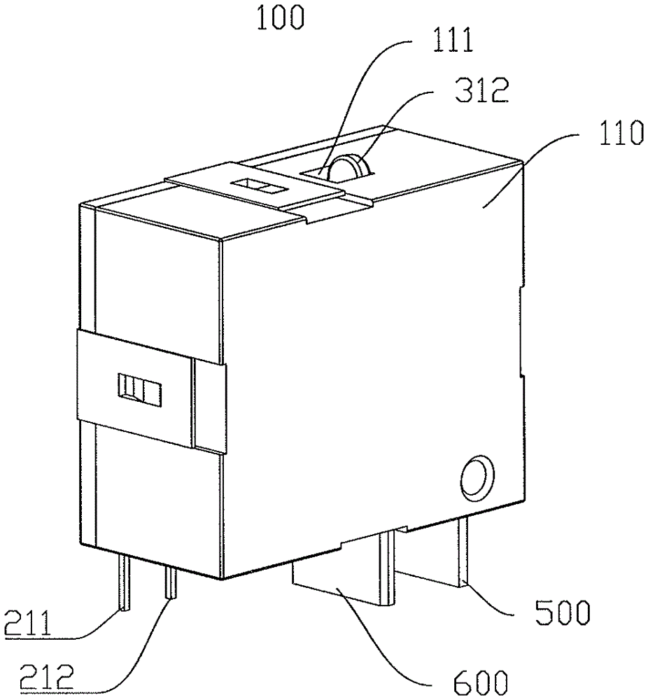
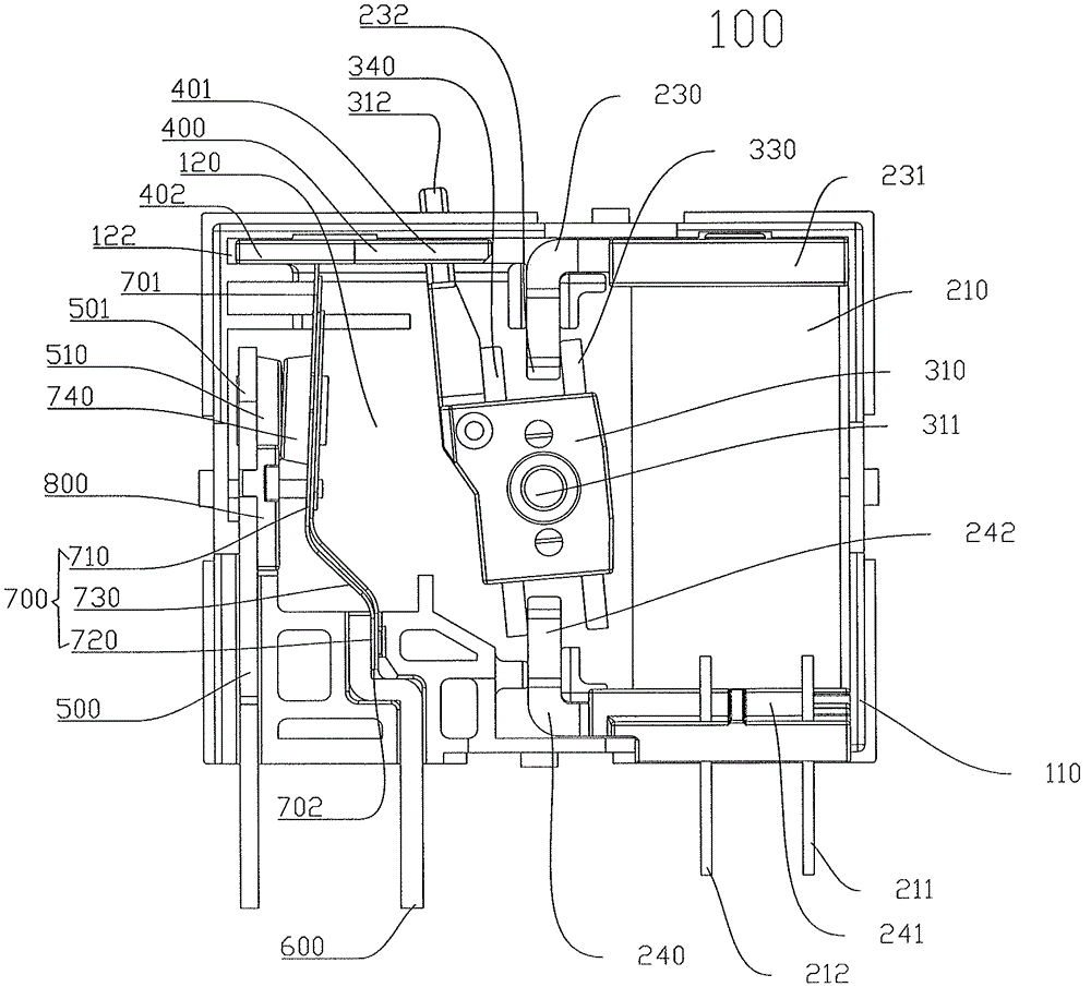
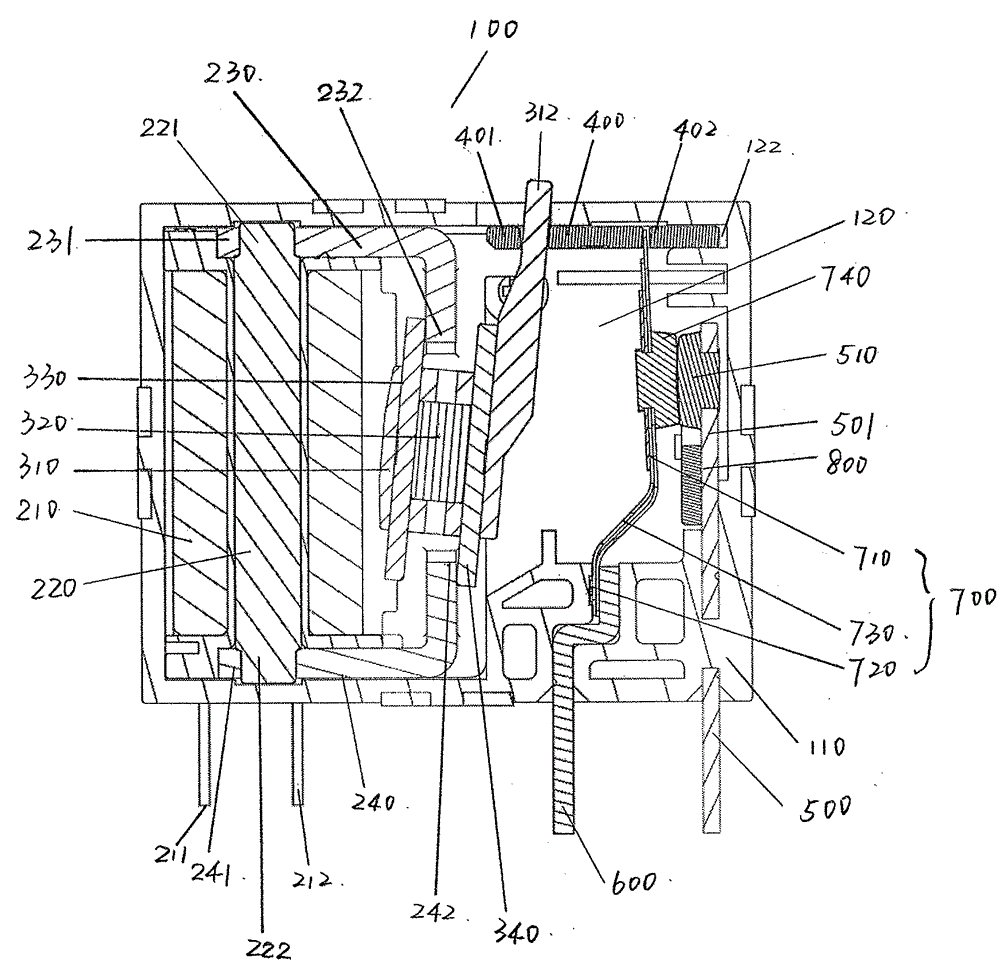
[0057] Such as figure 1 , figure 2 As shown, the electromagnetic relay 100 includes a housing 110 , and the housing 110 is provided with a cavity 120 . The cavity 120 is provided with Figure 5 The electromagnetic assembly 200 shown, Image 6 with Figure 7 Shown rotatable member 300 and Figure 8 to Figure 10 The switch assembly 900 is shown.

[0058] Such as figure 2 , image 3 , Figure 4 with Figure 5 As shown, the electromagnetic assembly includes a coil 210 , an iron core 220 , an L-shaped first yoke 230 and an L-shaped second yoke 240 . The coil 210 is arranged around the iron core 220, which is electrically connected with two contact pins (211, 212). Two pins (211, 212) are fixedly arranged on the housing 110. The two pins (211, 212) can be respectively connected to the positive and negative poles of the power supply, so as to generate cur...


PUM


Abstract

Disclosed is an electromagnetic relay, comprising: a stationary current-carrying plate fixedly arranged, wherein the stationary current-carrying plate is provided with a first end and a second end, and the first end of the stationary current-carrying plate is provided with a stationary contact; and a movable contact spring at least one end of which is movably arranged, the movable contact spring being provided with a movable contact, wherein at least one end of the movable contact spring on which the movable contact is arranged can be moved to enable the movable contact and the stationary contact to be arranged in a contacting manner or a separated manner. It is characterized in that a concentrating flux plate is arranged between the stationary current-carrying plate and the movable contact spring, the concentrating flux plate is arranged on the stationary current-carrying plate, on the movable contact spring, or between the stationary current-carrying plate and the movable contact spring and in the position which is not in contact with the stationary current-carrying plate and the movable contact spring. When the movable contact is in contact with the stationary contact to switch on a current, the concentrating flux plate can reduce the ampere force between the stationary current-carrying plate and the movable contact spring. The present invention can reduce the influence of ampere force, and maintain the security of an electromagnetic relay and a switch device.

Description

technical field [0001] The invention relates to an electromagnetic relay and a switch device. Background technique [0002] The magnetic latching electromagnetic relay is an electric control device, which has an interactive relationship between the control system (also known as the input circuit) and the controlled system (also known as the output circuit). Magnetic latching electromagnetic relay is generally composed of iron core, coil, yoke, armature, permanent magnet, contact reed and so on. Its working principle is: add a certain voltage at both ends of the coil, and a certain current flows through the coil, thereby generating an electromagnetic effect, and the armature will move under the interaction force of the electromagnetic force and the permanent magnet, thereby driving the moving contact and the static contact. The contacts are in contact and the controlled circuit is turned on. When the coil is powered off, the electromagnetic attraction force also disappears,...

Claims


Application Information

Patent Timeline
Patent Type & Authority Patents(China)
IPC IPC(8): H01H50/16H01H50/56
CPCH01H1/54H01H50/42H01H50/56H01H51/2227
Inventor 张晓宁胡协力
Owner TYCO ELECTRONICS SHENZHEN
Why Eureka
Try Eureka