
Method and device for controlling optical network fault line

A faulty line and optical network technology, applied in the field of optical network, can solve the problems of power consumption control of faulty single boards that cannot guarantee line safety and faulty lines, and achieve the effect of ensuring equipment safety and reducing energy consumption

Inactive Publication Date: 2013-10-30
ZTE CORP
View PDF1 Cites 2 Cited by
  • Summary
  • Abstract
  • Description
  • Claims
  • Application Information

AI Technical Summary

Problems solved by technology

[0006] The purpose of the present invention is to provide a control method and device for a faulty line in an optical network, so as to solve the technical problem that the prior art cannot control the power consumption of the faulty single board of the faulty line and cannot guarantee the safety of the line

Method used


Image

  • Method and device for controlling optical network fault line
  • Method and device for controlling optical network fault line
  • Method and device for controlling optical network fault line

Examples


Embodiment Construction

[0039] In order to make the technical problems, technical solutions and beneficial effects to be solved by the present invention clearer and clearer, the present invention will be further described in detail below in conjunction with the accompanying drawings and embodiments. It should be understood that the specific embodiments described here are only used to explain the present invention, not to limit the present invention.

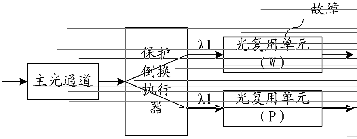
[0040] Figure 5 It is a flow chart of the control method for the faulty line of the optical network in the preferred embodiment of the present invention. Such as Figure 5 Shown, the method of preferred embodiment of the present invention comprises the following steps:

[0041] Step S501: the working line of the optical network system fails;

[0042] The aforementioned working lines may include 1+1 multiplex section protection working lines, 1+1 channel section protection working lines or 1+1 optical data unit protection working lines in the optical...


PUM


Abstract

The invention discloses a method and device for controlling an optical network fault line. The method comprises the steps that when the working line fails, a protection switching controller reads a fault indication of the fault line and sends out a power source control signal to a corresponding fault device according to the fault indication, and after the fault device receives the power source control signal, a corresponding power source module on the fault device is closed according to the power source control signal. According to the method and device for controlling the optical network fault line, the energy consumption control over the device on the fault line can be carried out, therefore, the device safety of the fault line can be ensured, the energy consumption is reduced, and energy is saved and protected.

Description

technical field [0001] The invention relates to the technical field of optical networks, in particular to a method and device for controlling a faulty line of an optical network. Background technique [0002] With the rapid development of optical fiber communication technology, the stable operation and equipment protection capabilities of optical network systems are becoming more and more important. The Chinese invention patent with the publication number CN 101640818 discloses an optical network protection device and protection method, which realizes the protection switching of optical network equipment when a fault occurs. Protection switching can ensure that services will not be interrupted when network equipment or working lines are abnormal. During the process of protection switching, the processing of faulty services and faulty single boards is involved. [0003] figure 1 It is a schematic diagram of the working circuit of the chain network in the optical network sy...

Claims


Application Information

Patent Timeline
Patent Type & Authority Applications(China)
IPC IPC(8): H04B10/03H04B10/038
Inventor 刘真南
Owner ZTE CORP
Learn More