
Yarn tension detector

A yarn tension and detector technology, applied in the textile field, can solve the problems of yarn breakage, contamination, yarn knots, etc., and achieve the effects of preventing breakage, preventing damage, and being easy to operate.

Inactive Publication Date: 2013-11-06
JIANGSU ZHONGXIN RESOURCES GRP
View PDF10 Cites 5 Cited by
  • Summary
  • Abstract
  • Description
  • Claims
  • Application Information

AI Technical Summary

Problems solved by technology

[0002] When the traditional yarn is wound and unwound, the speed of the winding wheel is too large or too small, too fast will cause the yarn to be broken, and too slow will cause the yarn to be knotted or stained due to lack of corresponding tension

Method used

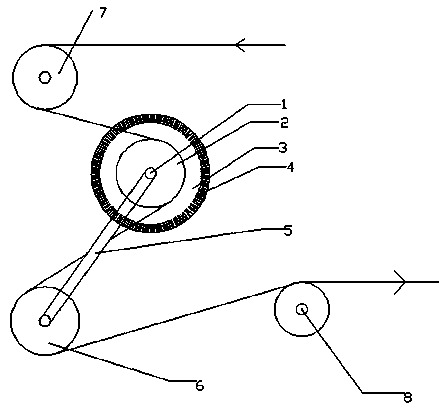

Image

  • Yarn tension detector
  • Yarn tension detector
  • Yarn tension detector

Examples


Embodiment Construction

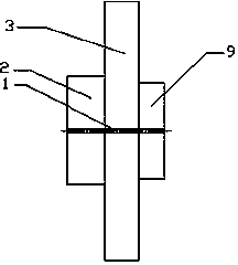
[0017] Such as figure 1 with 3 As shown, the yarn tension detector includes a fixed guide wheel 2, a fixed shaft rod 1, a tension wheel 6, a tension connecting rod 5, a scale wheel 3, and a rotation sensor 9, wherein the fixed guide wheel 2, the scale wheel 3 and the rotation sensor 9 is coaxially installed on the fixed shaft rod 1, wherein the fixed guide wheel 2 can rotate on the fixed shaft rod 1, while the fixed end of the scale wheel 3 and the rotation sensor 9 are fixed on the fixed shaft rod 1, and the tension link 5 is fixedly connected with the rotation sensing end of the rotation sensor 9, the other end of the tension link 5 is provided with a tension wheel 6, and scales 4 are evenly distributed on the scale wheel 3.

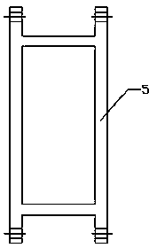
[0018] Such as figure 2 As shown, the tension link is a duplex structure, with holes for connecting with the shaft at both ends, and a rectangular wire slot in the middle.

[0019] When using as figure 1 As shown, the yarn is transmitted to the ya...


PUM


Abstract

The invention discloses a yarn tension detector. According to the yarn tension detector, a fixed guide wheel, a tension pulley and a tension connecting rod are combined to monitor yarn tension in the yarn conveying process so as to control the adjustment of the rotational speed of a yarn inlet wheel and the tension of yarn. The yarn tension detector has the advantages of being simple in structure, convenient to operate and suitable for the transformation of multiple textile machines and coiling machines.

Description

technical field [0001] The invention relates to a yarn tension detector, which belongs to the textile field. Background technique [0002] When the traditional yarn is wound and unwound, the speed of the winding wheel is too large or too small, too fast will cause the yarn to be broken, and too slow will cause the yarn to be knotted or stained due to lack of corresponding tension . Contents of the invention [0003] The present invention provides a device that can solve the above technical problems. [0004] The present invention is realized by following method: [0005] A yarn tension detector, comprising a fixed guide wheel, a fixed shaft rod, a tension wheel, a tension connecting rod and a rotation sensor, the fixed guide wheel is fixed to the fixed shaft rod in rotation, and one end of the tension connecting rod is fixed to the The fixed axis rod is rotationally connected, the other end of the tension connecting rod is provided with a tension wheel, and a rotation s...

Claims


Application Information

Patent Timeline
Patent Type & Authority Applications(China)
IPC IPC(8): G01L5/06
Inventor 朱卫强
Owner JIANGSU ZHONGXIN RESOURCES GRP
Learn More