
Method for obtaining 3D imaging image from single 2D image

An image and 3D technology, applied in image communication, electrical components, stereo system, etc.

Active Publication Date: 2013-11-06
CENT SOUTH UNIV
View PDF2 Cites 15 Cited by
  • Summary
  • Abstract
  • Description
  • Claims
  • Application Information

AI Technical Summary

Problems solved by technology

[0006] The technical problem to be solved by the present invention is to provide a method for obtaining a 3D imaging image from a single 2D image, which overcomes the problem in the prior art that the conversion process from a 2D image to a 3D image usually requires the use of image depth clues to obtain depth information, thereby providing a better viewer experience. Or bring a better visual experience than ordinary 2D images

Method used


Image

  • Method for obtaining 3D imaging image from single 2D image
  • Method for obtaining 3D imaging image from single 2D image
  • Method for obtaining 3D imaging image from single 2D image

Examples


Embodiment 1

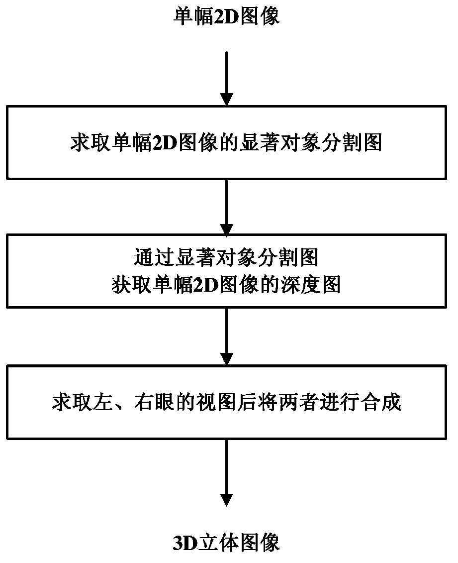
[0072] This embodiment is for a single 2D image, such as figure 1 As shown in the method for obtaining a 3D imaging image from a single 2D image, the process of obtaining the corresponding left-eye view and right-eye view is carried out in the following three steps:

[0073] Step A: Obtain a salient object segmentation map of a single 2D image

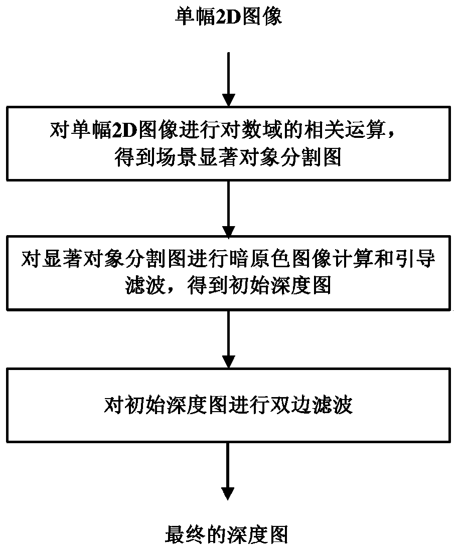
[0074] The calculation of the salient object segmentation map is as follows: figure 2 The first step in the specific process of depth map estimation shown includes the following steps:

[0075] Step A1: Convolute the single 2D image with a Gaussian low-pass smoothing function to obtain the luminance component image of the single 2D image

[0076] L ^ c ( x , y ) = I c ( x , y ) ...

Embodiment 2

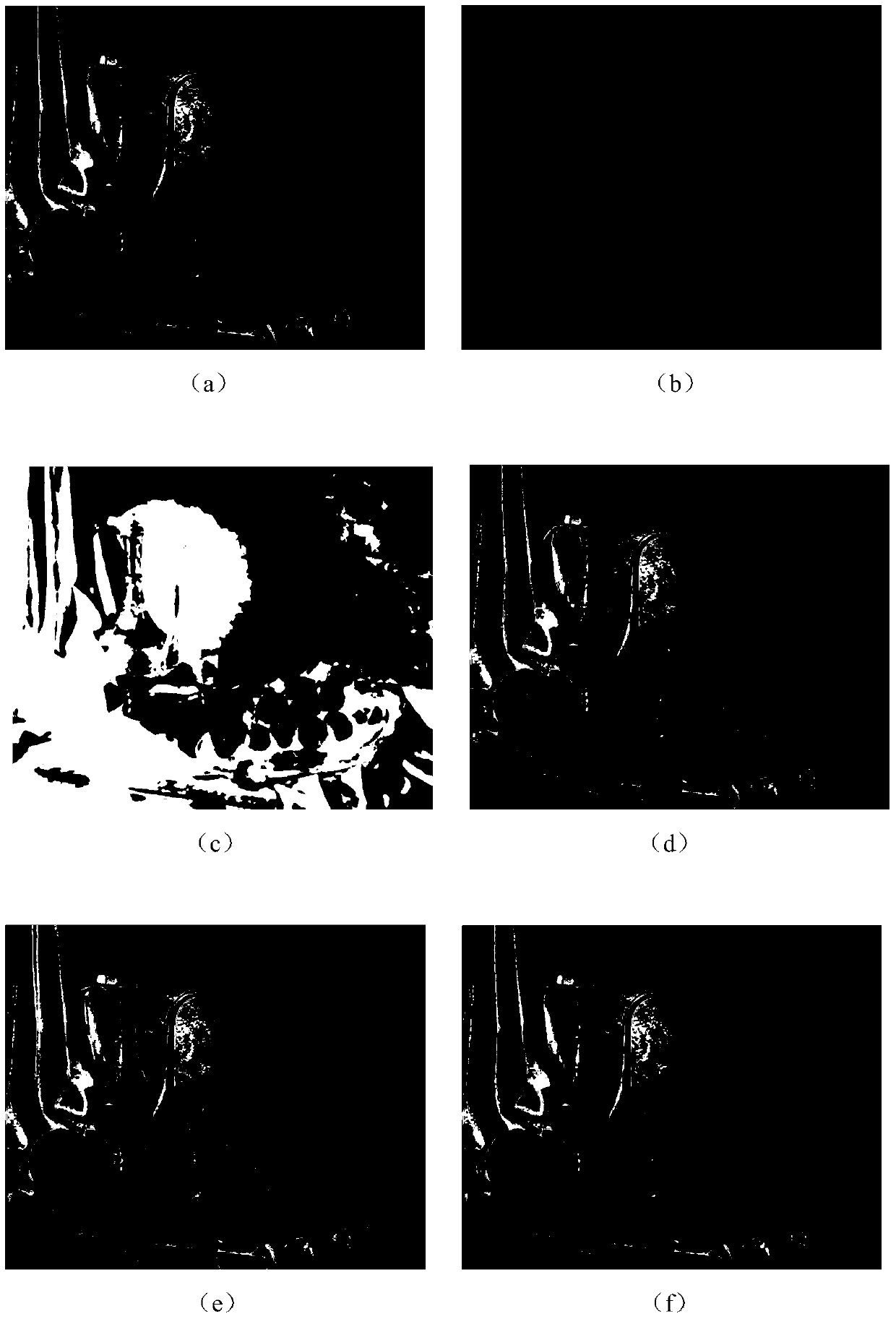
[0114] For a single 2D image Figure 4 (a) (size 800×500) for 3D conversion processing. First, the original 2D image is convoluted with a Gaussian low-pass smoothing function to obtain the brightness component image of the original image. Among them, the standard deviation σ of the Gaussian low-pass smoothing function is 9, the smoothing window size w is set to 55, and the center m of the window is set to 28. Then use formula 4 to get a new brightness component image, where ω 1 Set to 3. Finally, the correlation operation in the logarithmic domain is carried out to obtain Figure 4 Salient object segmentation of (a) Figure 4 (b).

[0115] Then, the salient objects are segmented Figure 4 (b) On the three color channels of R, G, and B, use a window with a size of 3×3 to perform minimum value filtering, and use the minimum value of the corresponding pixel points of the three images obtained after filtering as the pixel of the corresponding point of the dark primary color ...

Embodiment 3

[0118] For a single 2D image Figure 5 (a) (size 470×500) for 3D conversion processing. First, a single 2D image is convolved with a Gaussian low-pass smoothing function to obtain the brightness component image of the original image. Among them, the standard deviation σ of the Gaussian low-pass smoothing function is 5, the smoothing window size w is set to 31, and the center m of the window is set to 16. Then use formula (4) to get a new brightness component image, where ω 1 Set to 2. Finally, the correlation operation in the logarithmic domain is carried out to obtain Figure 5 Salient object segmentation of (a) Figure 5 (b).

[0119] Then, the salient objects are segmented Figure 5 (b) On the three color channels of R, G, and B, use a window with a size of 3×3 to perform minimum value filtering, and use the minimum value of the corresponding pixel points of the three images obtained after filtering as the pixel of the corresponding point of the dark primary color ima...


PUM


Abstract

The invention discloses a method for obtaining a 3D imaging image from a single 2D image. The method includes the following steps of firstly, obtaining a significant object segmentation image of the single 2D image; secondly, obtaining a depth image of the single 2D image through the significant object segmentation image obtained in the first step; thirdly, obtaining a left eye vision view required by 3D imaging and a right eye view required by 3D imaging through the depth image obtained in the second step, and combining the left eye view and the right eye view to obtain a 3D image corresponding to the single 2D image, wherein the produced depth image does not restore real depth information but is just a pseudo depth image which reflects the relative position relationship of an object in the image and other parts in the scene. Through a large number of experiments, the experiment result expresses that the corresponding 3D image has an obvious three-dimensional effect after the left eye view produced through the pseudo depth image is combined with the right eye view produced through the pseudo depth image.

Description

technical field [0001] The invention belongs to the field of image information processing, and in particular relates to a method for acquiring a 3D imaging image from a single 2D image. Background technique [0002] 3D video signal processing has become an important hot issue in current visual processing. With the rapid development of 3D technology, 2D images that can only present flat images can be presented in a three-dimensional manner, thereby bringing viewers a more realistic and unique visual experience. Therefore, 3D technology is widely used in many fields. For example, 3D technology has become a major trend in today's film development, but the lack of film sources has become the main bottleneck restricting the rise of the film industry. Converting 2D movies to 3D movies can not only greatly increase the themes and quantity of digital stereoscopic movies, but also allow some classic old movies to re-appear on the screen in new forms to shine. The video game indust...

Claims


Application Information

Patent Timeline
IPC IPC(8): H04N13/00H04N15/00
Inventor 郭璠唐琎蔡自兴
Owner CENT SOUTH UNIV
Learn More