Lifting stationarity control system and mining dump truck

A technology of control system and stability, which is applied in the direction of vehicles with inclined load bearing, can solve the problems of buffer sleeve occupying lifting stroke, increasing the complexity of lifting cylinder, and buffering structure losing its function, so as to avoid small rotation angle and compensate Manufacturing error, easy-to-control effects

Inactive Publication Date: 2013-11-13
SANY HEAVY EQUIP
View PDF11 Cites 22 Cited by
  • Summary
  • Abstract
  • Description
  • Claims
  • Application Information

AI Technical Summary

Problems solved by technology

However, the above methods all have certain disadvantages: 1. Designing a buffer structure in the lift cylinder increases the complexity of the lift cylinder, and the buffer sleeve occupies the lift stroke, which affects the tipping angle of the carriage, and the throttle hole affects The assembly of the sliding bushing; on the other hand, in order to compensate for the manufacturing error and prevent the cylinder from hitting, the lifting cylinder is equipped with a safety stroke, that is, when the carriage is completely lowered, the lifting cylinder cannot be fully retracted, which will make the end of the descending stroke The buffer structure fails
2. Set the proximity switch at the end of the lifting and lowering stroke. In order to improve the dumping efficiency, the driver generally depresses the accelerator to the bottom during the actual operation, so that the carriage and materials obtain a greater speed and inertia. When the main spool moves, it has already passed the control point, which makes the throttling buffer lose its effect; 3. Through the human intervention of the proportional electric control handle, since the lifting handle has four working positions: "lift", "hold", "floating" ", "forced landing", the swing angle that can be assigned to each position is limited, even if the handle is pulled slightly, the lifting spool will get a large input signal, and the controllability of the spool is poor

Method used


Image

  • Lifting stationarity control system and mining dump truck

Examples


Embodiment Construction

[0024] The following will clearly and completely describe the technical solutions in the embodiments of the present invention with reference to the accompanying drawings in the embodiments of the present invention. Obviously, the described embodiments are only some, not all, embodiments of the present invention. Based on the embodiments of the present invention, all other embodiments obtained by persons of ordinary skill in the art without creative efforts fall within the protection scope of the present invention.

[0025] It should be noted that, in the case of no conflict, the embodiments of the present invention and the features in the embodiments can be combined with each other.

[0026] Embodiments of the present invention will be specifically explained below in conjunction with the accompanying drawings.

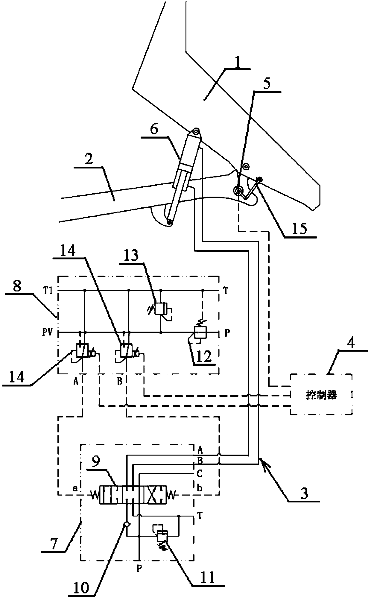
[0027] like figure 1 A lifting stability control system according to an embodiment of the present invention shown in , includes a carriage 1 , a vehicle frame 2 , a l...


PUM


Abstract

The invention discloses a lifting stationarity control system and a mining dump truck and belongs to the field of mechanical control. The Lifting stationarity control system comprises a truck bed 1, a frame 2, a lifting mechanism 3, a controller 4, and an angular displacement sensor 5, wherein the truck bed 1 is hinged to the frame 2; the lifting mechanism 3 can extend and contract to drive the truck bed 1 to ascend or descend relative to the frame 2; the controller 4 is connected with the lifting mechanism 3; the angular displacement sensor 5 is arranged on the truck bed 1 and the frame 2 and is connected with the controller 4; the angular displacement sensor 5 is used for detecting an angular displacement signal of the truck bed 1 relative to the frame 2 and transmitting the signal to the controller 4; and the controller 4 is used for controlling the movement velocity of the truck bed 1 through the lifting mechanism 3 according to the signal. According to the technical scheme of the invention, angle valves collected by the angular displacement sensor are used as controller input signals and signal acquisition section is wide, so that the defects that the rotation angle of an electronic control handle is small and the controllability of a value element is bad are avoided, the effects of throttling and buffering are realized, and the service life of parts is prolonged.

Description

[0001] The invention belongs to the field of mechanical equipment control, and relates to a stability control system, in particular to a lifting stability control system and a dump truck. Background technique [0002] Mining dump truck is a mining transport vehicle, which belongs to one of the mining equipment. It is mainly used in open-pit mines to complete the tasks of rock and earth stripping and ore transportation. Water conservancy projects have the characteristics of short travel distance, small turning radius, heavy load, and large geometric size. [0003] The lifting and unloading of the vehicle are driven by the hydraulic system. The lifting hydraulic system includes power components: hydraulic pumps, control components: lift valves, lift pilot valves, etc., executive components: hydraulic cylinders, working medium: hydraulic oil , and hydraulic accessories such as filters and filters. [0004] During the movement of the carriage, due to the certain speed and inertia...

Claims


Application Information

Patent Timeline
Patent Type & Authority Applications(China)
IPC IPC(8): B60P1/16
Inventor 邓辉田秀峰高天林黄志怀满军城
Owner SANY HEAVY EQUIP
Why Eureka
Try Eureka