Aircraft keel beam

An aircraft and keel technology, applied in the field of keel beams, can solve the problems of not allowing deformation and increasing stress, and achieve the effect of optimizing the size

Active Publication Date: 2013-11-13
AIRBUS OPERATIONS SAS
View PDF6 Cites 1 Cited by
  • Summary
  • Abstract
  • Description
  • Claims
  • Application Information

AI Technical Summary

Problems solved by technology

[0010] According to another disadvantage, the keel beam and the center wing box are connected by means of splice plates, which do not allow any slight deformation around the axis parallel to the longitudinal direction
The stiffness of the connection between the center wing box and the keel leads to increased stresses in the keel region caused by the bending forces of the wing

Method used


Image

  • Aircraft keel beam
  • Aircraft keel beam
  • Aircraft keel beam

Examples


Embodiment Construction

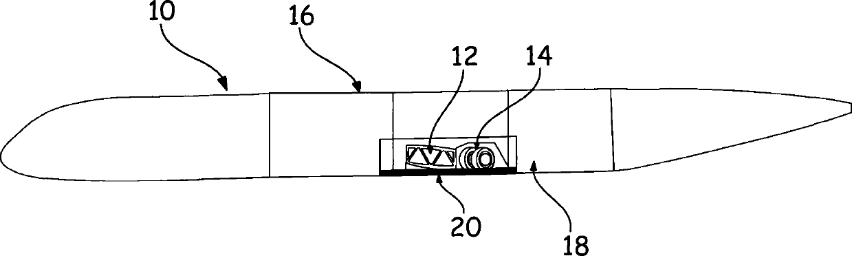
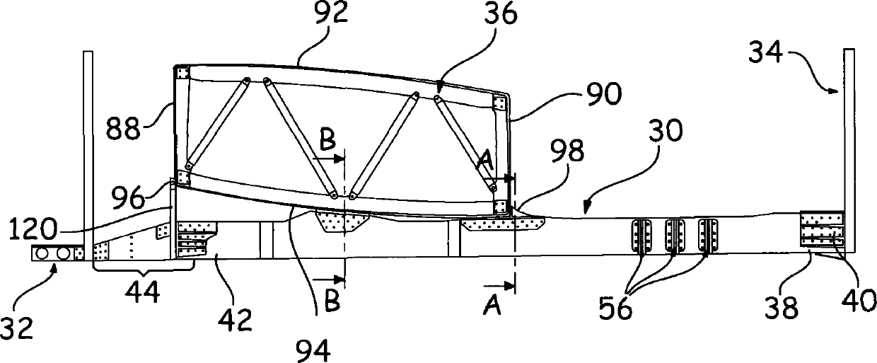
[0029] image 3 A keel beam 30 for connecting a front structure 32 and a rear structure 34 of the aircraft is shown. The keel beam 30 is connected to a center wing box 36 . The joist beam 30 includes a rear end 38 connected to the rear structure 34 by means of a splice plate 40 and a front end 42 connected to the front structure 32 by means of an assembly of stiffeners and splice plates 44 .

[0030] The keel beam 30 is made of composite material to reduce the onboard mass. Alternatively, the joist beams may be metallic and obtained by bending, extruding, pressure forming, explosion forming or the like.

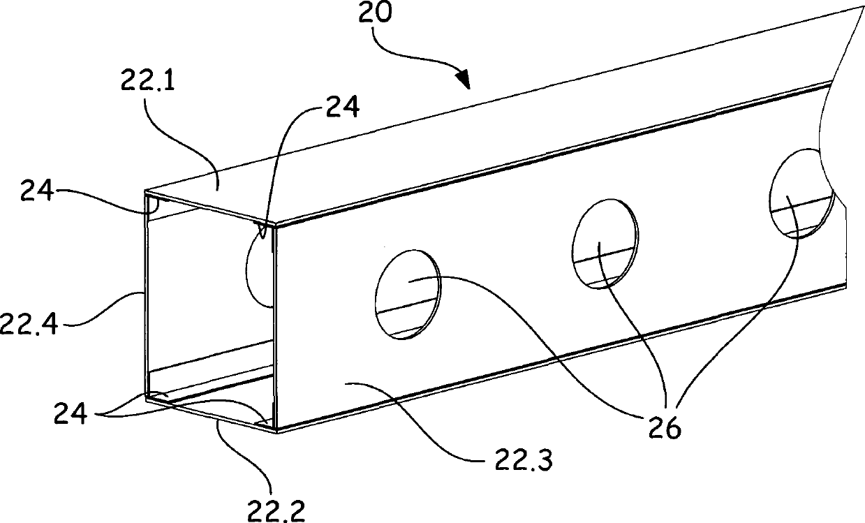
[0031] According to the invention, the joist beam 30 comprises on the one hand a first U-shaped portion 46 , hereafter referred to as the body, having a horizontal bottom 48 and two solid side walls 50 , 50 ′, and on the other hand a second portion, referred to as the cover. Portion 52 , which together with body 46 defines a closed portion and includes opening 54 for acces...


PUM


Abstract

A keel beam connected to a central wing box of an aircraft and ensuring the connection between a front structure and a rear structure of an aircraft is characterized in that it includes, on the one hand, a U-shaped body with a horizontal base and two solid lateral walls, and on the other hand, a cover which has a U shape oriented in the same manner as the body, with a base in the lower portion and curved edges, the ends of which are oriented upward so that each curved edge includes an outer surface flattened against and fixed to the inner surface of the lateral walls in order to define, with the body, a closed section, the cover including openings for accessing the inside of the keel beam.

Description

technical field [0001] The invention relates to a keel beam of an aircraft. Background technique [0002] figure 1 A schematic diagram of a fuselage 10 of an aircraft is shown with a center wing box 12 providing the connection between the fuselage and the wings and a landing gear housing 14 . [0003] For the remainder of the description, the longitudinal direction will be understood as the direction corresponding to the largest dimension of the fuselage. A transverse plane is a plane perpendicular to the longitudinal direction. The front of the aircraft corresponds to the front end of the fuselage, while the rear corresponds to the tail unit. [0004] On either side of the center wing box 12 and / or the landing gear housing 14, the fuselage 10 comprises a first section 16 arranged at the front and a second section 18 arranged at the rear, the two sections 16 and 18 being arranged centrally The keel beam 20 below the wing box 12 is connected. [0005] according to figu...

Claims


Application Information

Patent Timeline
IPC IPC(8): B64C1/26
CPCB64C1/06B64C3/185B64C1/00B64C1/065B64C1/26
Inventor 伊夫·迪朗德尼·苏拉热罗姆·科尔芒格罗
Owner AIRBUS OPERATIONS SAS
Why Eureka
Try Eureka