
Dual-band interspersed cellular basestation antennas

A technology for cellular base stations and antennas, applied in the directions of antennas, resonant antennas, antenna coupling, etc., can solve the problems of many antennas, difficulty in approving new locations, and visual pollution of antennas, and achieve the effect of optimizing size

Active Publication Date: 2014-09-24
COMMSCOPE TECH LLC
View PDF10 Cites 8 Cited by
  • Summary
  • Abstract
  • Description
  • Claims
  • Application Information

AI Technical Summary

Problems solved by technology

This results in too many antennas being installed in one location
Due to the visual pollution of so many antennas, the local government imposed restrictions and made it difficult to approve new locations
Some antenna designs attempt to combine the two frequency bands and extend the bandwidth, however, due to the proliferation of many air interface standards and frequency bands, many antennas are still required

Method used


Image

  • Dual-band interspersed cellular basestation antennas
  • Dual-band interspersed cellular basestation antennas
  • Dual-band interspersed cellular basestation antennas

Examples


Embodiment Construction

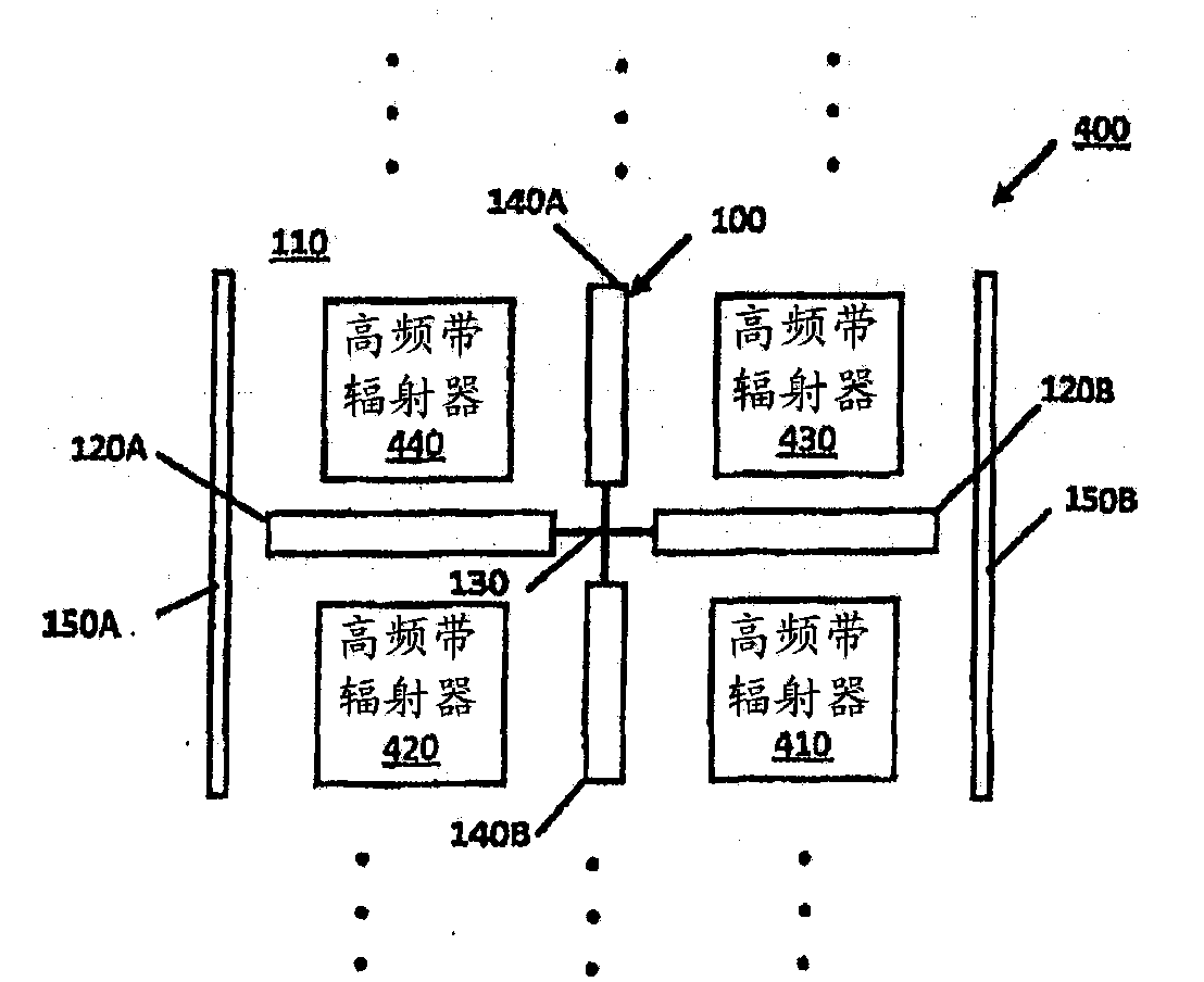
[0030] In the following, low-band radiators for ultra-wideband dual-band dual-polarized cellular base station antennas and such dual-band cellular base station antennas are disclosed. In the following description, numerous specific details are set forth, including specific horizontal beamwidths, air interface standards, dipole arm shapes and materials, dielectric materials, and the like. However, those skilled in the art can understand from the present disclosure that modifications and / or substitutions can be proposed without departing from the scope and spirit of the present invention. In other instances, specific details may be omitted in order not to obscure the invention.

[0031] As used below, "low band" refers to a low frequency band, such as 698~960 MHz, and "high band" refers to a high frequency band, such as 1710 MHz~2690 MHz. A "low-band radiator" refers to a radiator for such a low-frequency band, and a "high-band radiator" refers to a radiator for such a high-fre...


PUM


Abstract

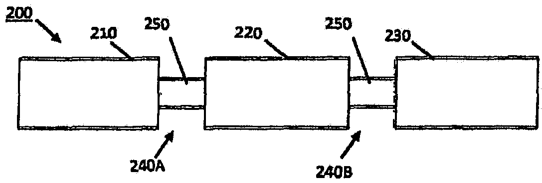
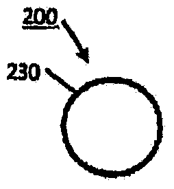
Low-band radiators (100) of an ultra- wideband dual-band dual-polarization cellular basestation antenna (400) and ultra-wideband dual-band dual-polarization cellular base-station antennas (400) are provided. The dual bands comprise low and high bands. The low-band radiator (100) comprises a dipole (120, 140) comprising two dipole arms (120A, 120B, 140A, 140B) adapted for the low band and for connection to an antenna feed. At least one dipole arm (200) of the dipole (120, 140) comprises at least two dipole segments (210, 220, 230) and at least one radiofrequency choke (240A, 240B). The choke (240A, 240B) is disposed between the dipole segments (210, 220, 230). Each choke (240 A, 240B) provides an open circuit or a high impedance separating adjacent dipole segments (210, 220, 230) to minimize induced high band currents in the low-band radiator (210, 220, 230) and consequent disturbance to the high band pattern. The choke (240A, 240B) is resonant at or near the frequencies of the high band.

Description

technical field [0001] This invention relates generally to antennas for cellular systems, and more particularly to antennas for cellular base stations. Background technique [0002] Advances in wireless technology generally require wireless operators to deploy new antenna equipment in their networks. On the downside, the tower becomes cluttered with multiple antennas, and at the same time, installation and maintenance become more complicated. Base station antennas generally cover a single narrow band. This results in too many antennas being installed in one location. Due to the visual pollution from so many antennas, the local government imposed restrictions and made it difficult to approve new locations. Some antenna designs attempt to combine the two frequency bands and extend the bandwidth, however, due to the proliferation of many air interface standards and frequency bands, many antennas are still required. Contents of the invention [0003] The following definiti...

Claims


Application Information

Patent Timeline
IPC IPC(8): H04B3/00
CPCH01Q5/00H04B3/00H01Q5/42H01Q21/26H01Q5/321H01Q1/246H01Q1/52H01Q21/30H01Q9/16
Inventor 尚春辉B·B·琼斯O·依斯克
Owner COMMSCOPE TECH LLC
Learn More