Miniaturized high-sensitivity piezoelectric microphone
A high-sensitivity, piezoelectric technology, applied to piezoelectric/electrostrictive transducers, microphones, electrical components, sensors, etc., can solve the problems of reducing and reducing the sensitivity of microphones, so as to reduce the device area and facilitate signal acquisition , the effect of reducing the size
- Summary
- Abstract
- Description
- Claims
- Application Information
AI Technical Summary
Problems solved by technology
Method used
Image
Examples
Embodiment 1
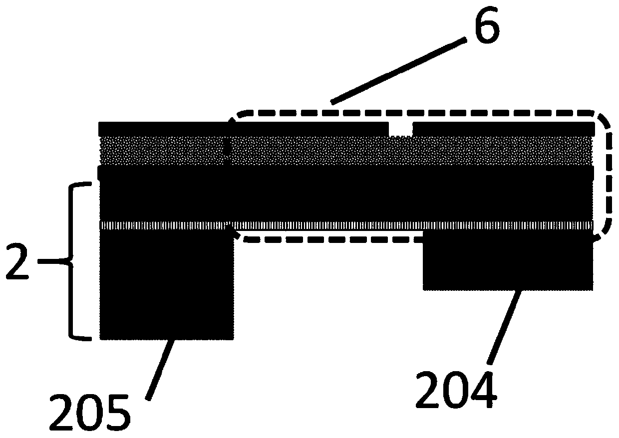
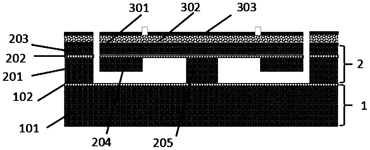
[0028] This embodiment discloses a structure of a miniaturized high-sensitivity piezoelectric microphone, such as figure 1 As shown, it includes an SOI wafer substrate 2 with a back cavity and a piezoelectric cantilever beam 6 fixed on the SOI wafer substrate 2. The piezoelectric cantilever beam 6 includes a fixed end fixedly connected with the SOI wafer substrate 2 and The free end connected to the fixed end and suspended above the back cavity is provided with a mass block 204 below the free end, and the resonant frequency of the device is reduced by adjusting the parameters of the mass block 204, thereby improving the sensitivity of the piezoelectric microphone. Usually, the substrate of the piezoelectric microphone can be selected from a variety of substrates, such as SOI, Si, and sapphire substrates, which are suitable for microphones with various structures, and the type of substrate can be determined according to the structure of the beam. The parameters of the adjusted ...
Embodiment 2
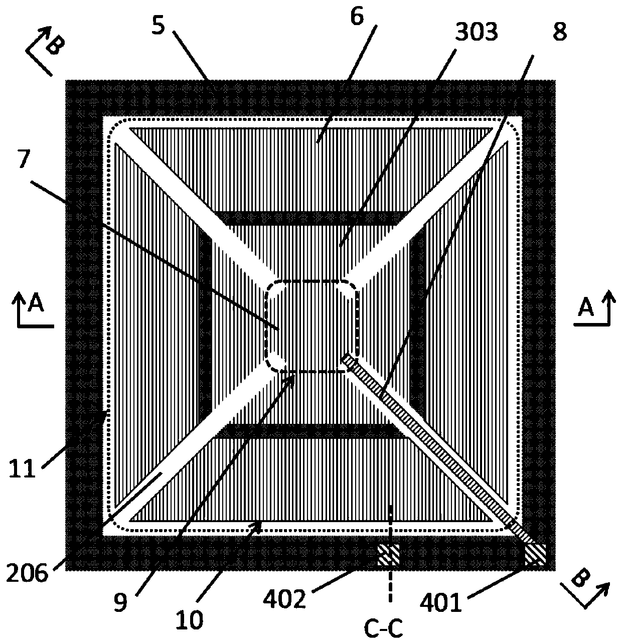
[0033] This embodiment discloses a piezoelectric microphone with four trapezoidal valves. Such as figure 2 As shown, there are multiple piezoelectric cantilever beams 6 , and there is a gap 206 of a certain width between adjacent piezoelectric cantilever beams 6 . Preferably, the shape of the piezoelectric cantilever beam 6 is fan-shaped, trapezoidal or triangular. The shape of the piezoelectric cantilever beam 6 in this embodiment is trapezoidal. Four trapezoidal piezoelectric cantilever beams 6 form the receiving sound pressure area 11, and the receiving sound pressure area can be be circles, triangles, squares or other polygons. The smaller end 9 of each piezoelectric cantilever 6 is fixedly connected to the substrate, and the other end is used as a free end, and each free end is provided with a mass block 204; of course, the larger end 10 can also be selected to be fixedly connected to the substrate. , and the other end as a free end.
[0034] The substrate of this exa...
Embodiment 3
[0039] refer to Figure 5 , four microphones of reduced size are connected in series, equal to the area of the prior art microphone, and the quality block 204 at the free end of the cantilever beam 6 has the effect of reducing the resonant frequency and improving the output voltage in the working range (20Hz~20kHz) to the device, by optimizing The quality block 204 makes the output performance of a single reduced-sized microphone consistent with that of the original large-area microphone. The four microphones are connected in series, and after the electrical signals generated by the four devices are superimposed on each other, the first signal terminal 404 and the second signal Terminal 405 can effectively enhance the microphone voltage sensitivity.
PUM
 Abstract
Description
Claims
Application Information
 - R&D
- Intellectual Property
- Life Sciences
- Materials
- Tech Scout
- Unparalleled Data Quality
- Higher Quality Content
- 60% Fewer Hallucinations
Browse by: Latest US Patents, China's latest patents, Technical Efficacy Thesaurus, Application Domain, Technology Topic, Popular Technical Reports.
© 2025 PatSnap. All rights reserved.Legal|Privacy policy|Modern Slavery Act Transparency Statement|Sitemap|About US| Contact US: help@patsnap.com


