Test board of micro-tillage machine

A test bench and micro-tiller technology, which is applied in the testing of machines/structural components, measuring devices, instruments, etc., can solve the problem of inability to accurately determine whether there is abnormal noise in the gear meshing in the gearbox, test interference of the micro-tiller, and engine noise. Large and other problems, to achieve the effect of preventing up and down vibration, reducing work vibration, and reducing noise interference

Inactive Publication Date: 2013-11-13
力帆科技(集团)股份有限公司
View PDF11 Cites 1 Cited by
  • Summary
  • Abstract
  • Description
  • Claims
  • Application Information

AI Technical Summary

Problems solved by technology

[0003] 1) The engine is noisy, and it is impossible to accurately judge whether there is any abnormal noise in the meshing of the gears in the gearbox, which interferes with the test;
[0004] 2) The micro-tiller is directly connected and fixed on the engine. The vibration of the micro-tiller is relatively large during running-in, and it will also generate vibration noise, which will interfere with the test of the micro-tiller;
[0005] 3) The test of the micro tillage machine needs to fix the engine first, and then connect and fix the micro tillage machine to the engine. The operation is cumbersome and the test efficiency is low.

Method used


Image

  • Test board of micro-tillage machine
  • Test board of micro-tillage machine
  • Test board of micro-tillage machine

Examples


Embodiment Construction

[0024] Below in conjunction with accompanying drawing and embodiment the present invention will be further described:

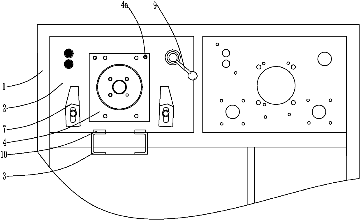
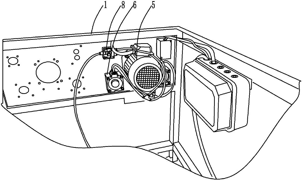
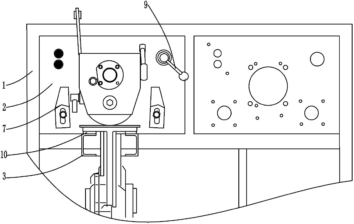
[0025] Such as Figure 1-Figure 4 As shown, the present invention is made up of stand 1, mounting plate 2, support block 3, flange plate 4, motor 5, cylinder 6, briquetting block 7, three-way valve 8, rotating handle 9, antivibration block 10 etc. Described platform 1 is square frame shape, and the upper part of platform 1 front and back sides is fixed with crossbeam, is longitudinally fixed with stiffener between the middle part of crossbeam and the middle part of top beam of platform 1 on the side, and between crossbeam and corresponding top There are two installation frames on the left and right formed between the beams. A mounting plate 2 is provided in each mounting frame, and the four sides of the mounting plate 2 are welded and fixed to the corresponding frame edges of the mounting frame. The lower part of the front of the mounting plate 2 protrudes ...


PUM


Abstract

The invention discloses a test board of a micro-tillage machine. A mounting plate (2) is mounted on a rack (1), and a pair of support blocks (3) extends perpendicularly and forwards at the lower part of the front side of the mounting plate (2); a flange plate (4) is arranged above the two support blocks (3); the flange plate (4) and a motor (5) on the back side of the mounting plate (2) are attached and fixed to the mounting plate (2); a driving shaft of the motor (5) is connected with a clutch in the middle of the flange plate (4); air cylinders (6) are evenly distributed on the left side and the right side of the motor (5); and piston rods of air cylinders (6) penetrate through the mounting plate (2) and then are movably sleeved with pressing blocks (7). According to the test board of the micro-tillage machine, the micro-tillage machine is assembled and fixed on the rack for testing, the assembling reliability of the micro-tillage machine is improved, vibration of the micro-tillage machine is reduced, and the testing accuracy is improved; and the air cylinders are used for controlling the assembly of the micro-tillage machine, the test board is simple, convenient and rapid, and the testing efficiency of the micro-tillage machine is improved.

Description

technical field [0001] The invention relates to a micro-tiller test bench, which is used for the clamping test of the micro-tiller. Background technique [0002] Existing tiller tests require the engine to be fixed on the platform first, and then the gearbox of the tiller is directly fixed on the engine, and then the engine drives the wheel shaft in the gearbox for running-in. Existing deficiency is as follows: [0003] 1) The engine is noisy, and it is impossible to accurately judge whether there is any abnormal noise in the meshing of the gears in the gearbox, which interferes with the test; [0004] 2) The micro-tiller is directly connected and fixed on the engine. The vibration of the micro-tiller is relatively large during running-in, and it will also generate vibration noise, which will interfere with the test of the micro-tiller; [0005] 3) To test the tiller, the engine should be fixed first, and then the tiller should be connected and fixed to the engine. The ope...

Claims


Application Information

Patent Timeline
Patent Type & Authority Applications(China)
IPC IPC(8): G01M99/00
Inventor 曹永仁陈璋明彭家秀
Owner 力帆科技(集团)股份有限公司
Why Eureka
Try Eureka