
Method and device for determining the inclined position of a vehicle

一种倾斜位置、车辆的技术,应用在测量装置、控制装置、测量倾斜度等方向,能够解决比较昂贵等问题,达到容易成本的效果

Active Publication Date: 2013-11-13
ROBERT BOSCH GMBH
View PDF6 Cites 4 Cited by
  • Summary
  • Abstract
  • Description
  • Claims
  • Application Information

AI Technical Summary

Problems solved by technology

This method for determining the swivel angle φ requires two rotational speed sensors and is therefore relatively expensive

Method used


Image

  • Method and device for determining the inclined position of a vehicle
  • Method and device for determining the inclined position of a vehicle
  • Method and device for determining the inclined position of a vehicle

Examples


Embodiment Construction

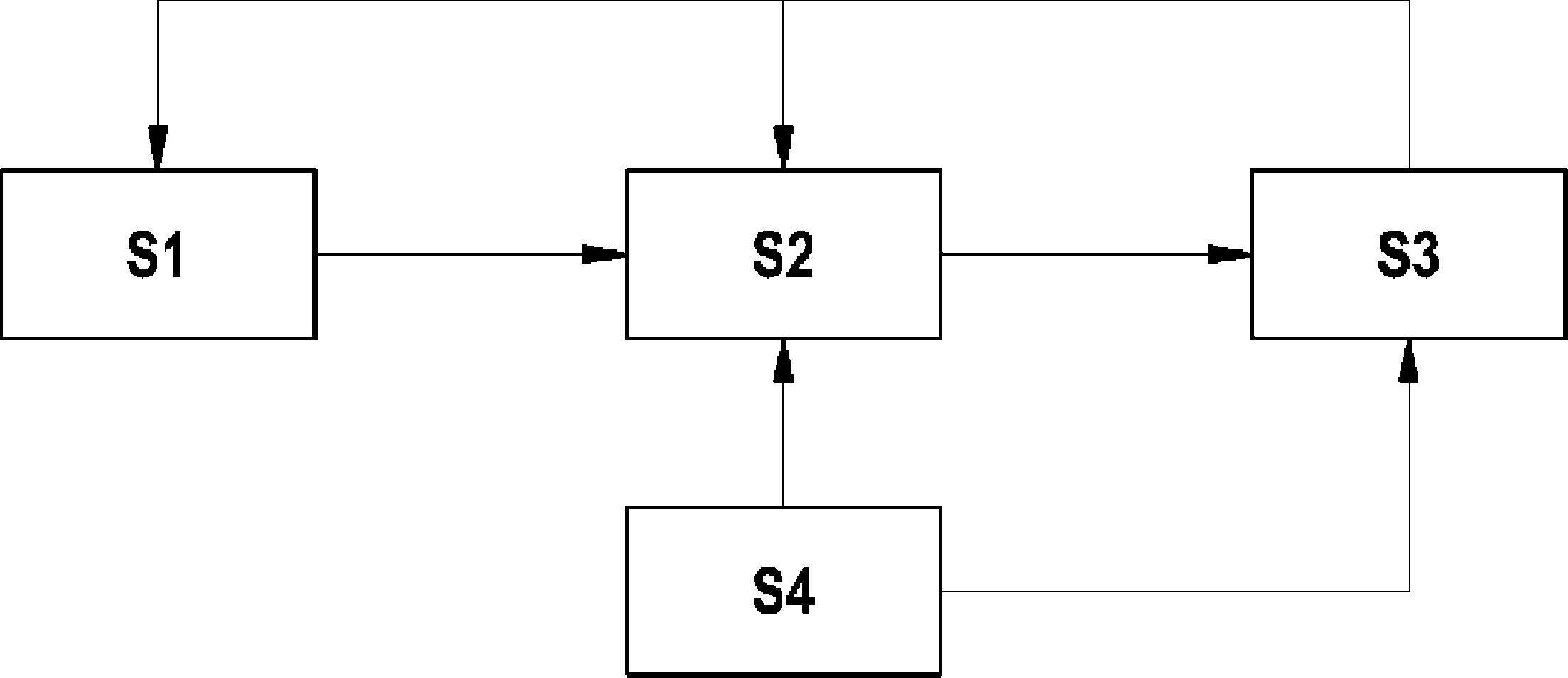
[0029] figure 1 A schematic block diagram of an embodiment of a method for determining the tilt position of a vehicle, not shown in detail, such as a motorcycle, is shown.

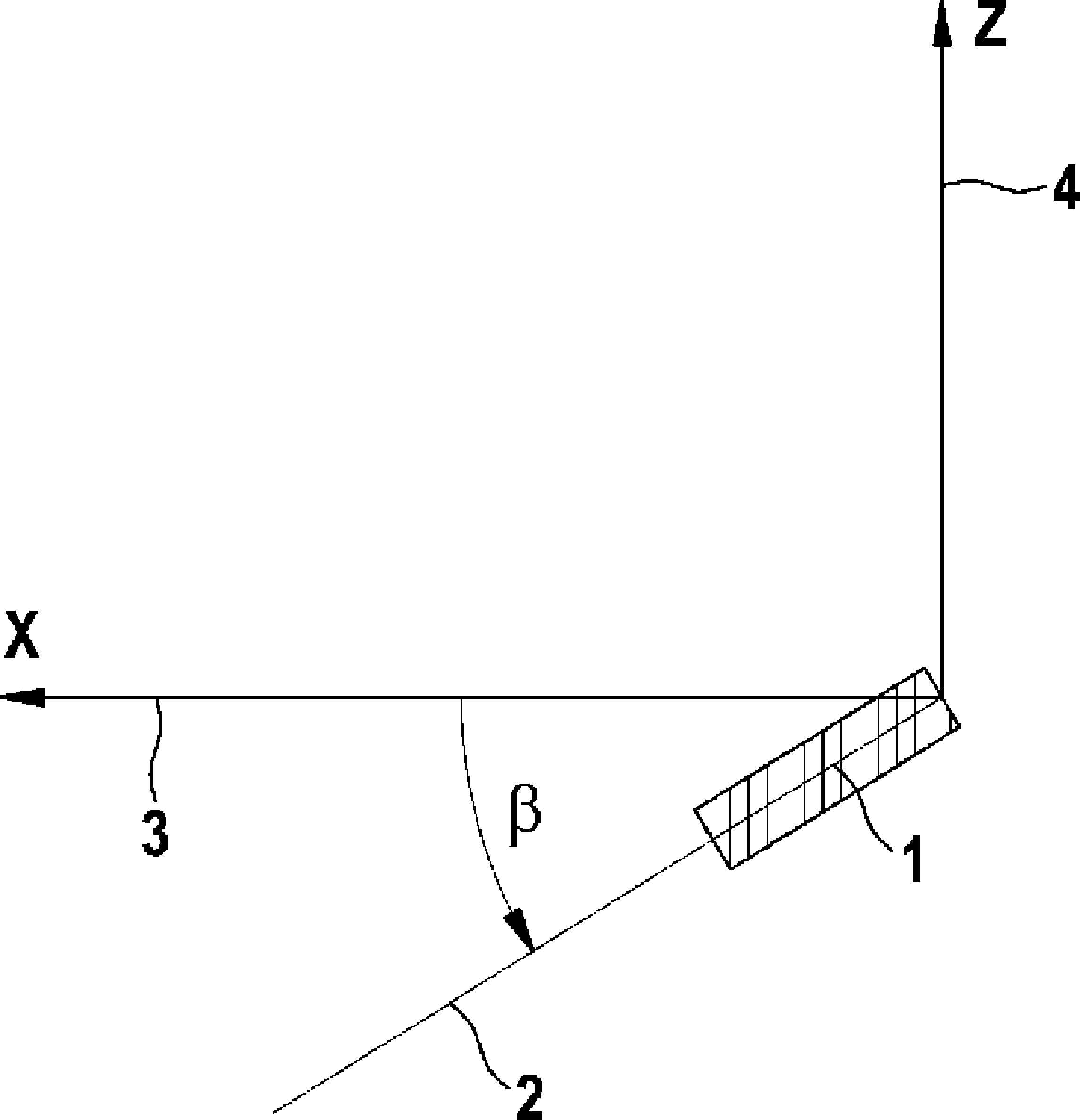
[0030] In the first step S1, use as in figure 2 The rotational speed ω is detected by the same rotational speed sensor 1 shown in . The rotational speed sensor 1 can be, for example, a piezoelectric or micromechanical sensor.

[0031] The measuring axis 2 of the sensor 1 lies in the x-z plane of the vehicle coordinate system, the x-direction 3 being defined by the longitudinal axis of the motorcycle and the z-direction 4 being defined by its vertical axis. The sensor thus measures not only a yaw ratio contribution but also a yaw ratio contribution, but not a pitch ratio contribution. The measuring signal ω of the rotational speed sensor 1 is obtained in the shown arrangement with the following equation:

[0032]

[0033] where W is the yaw rate W of the vehicle and G is its yaw rate G. The angle β...


PUM


Abstract

The invention relates to a method for determining the inclined position of a vehicle. A rotational speed (?), with a roll rate portion and a yaw rate portion, is detected by means of a sensor (1), the measurement axis (2) of said sensor being inclined by a pitch angle (ß) in relation to the longitudinal axis (3) of the vehicle. A roll angle (f) is finally determined from the rotational speed (?), to describe the inclined position of the vehicle.

Description

technical field [0001] The invention relates to a method for determining the tilt position of a vehicle, in particular a motor vehicle, and a device for carrying out the method. Background technique [0002] The tilted position of the vehicle is generally described by the pivot angle φ. It is known from the prior art to first measure the yaw rate W of the vehicle by means of a yaw rate sensor and to determine the yaw angle φ by subsequent integration of the yaw rate. However, the value determined in this way only represents the value Δφ by which the swivel angle changes during the integration phase. In contrast, without knowing the starting value φ at the beginning of the integration 0 (offset). Therefore, the calculated pivot angle φ has an offset error. In addition, all occurring errors are summed, since the changes in the swivel angle are correspondingly added to form the current value. The swing ratio is thus not long-term stable. A suitable determination of the pi...

Claims


Application Information

Patent Timeline
Patent Type & Authority Applications(China)
IPC IPC(8): B60W40/12B60W50/00B60W30/04
CPCB60W2520/10G01C9/00B60W40/12B60W2520/16B60W2050/0028B60W2030/043B60W2420/90
Inventor M.莱梅杰达
Owner ROBERT BOSCH GMBH
Learn More