Regenerative exhaust gas purification device

An exhaust gas purification device and regenerative technology, which is used in incinerators, waste heat treatment, lighting and heating equipment, etc., can solve the problems of complicated wiring engineering of electrical equipment, long time required for installation and assembly, and simplify installation. and assembly, the effect of reducing wiring work

Active Publication Date: 2013-11-13
SINTOKOGIO LTD
View PDF6 Cites 2 Cited by
  • Summary
  • Abstract
  • Description
  • Claims
  • Application Information

AI Technical Summary

Problems solved by technology

[0004] However, considering its use, the exhaust gas purification device is made large and is often installed outdoors. Therefore, there is a problem that it takes a long time to install and assemble on site.
In addition, the wiring work of electrical equipment is also complicated in order to switch the air supply and exhaust, and to control the ignition and extinguishment of the burner in the combustion chamber.

Method used


Image

  • Regenerative exhaust gas purification device
  • Regenerative exhaust gas purification device
  • Regenerative exhaust gas purification device

Examples


Embodiment Construction

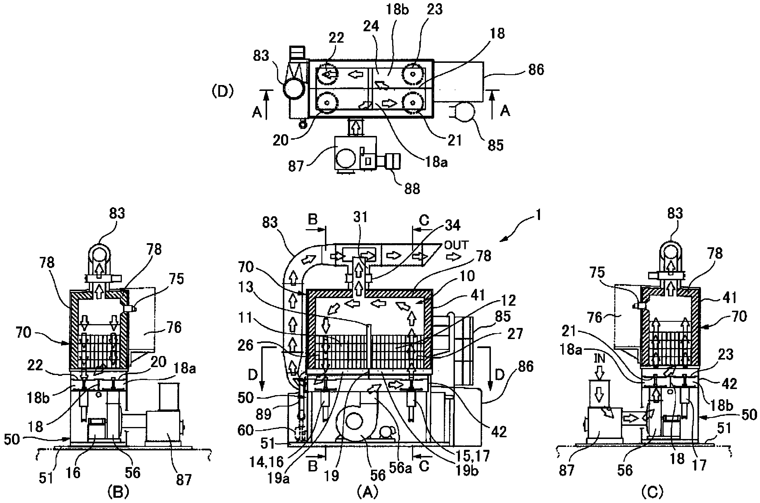
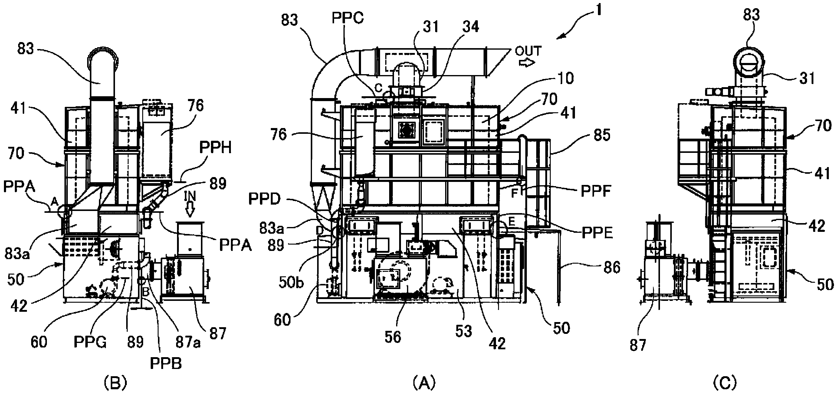
[0044] Hereinafter, a thermal storage type exhaust gas purification device according to an embodiment of the present invention will be described with reference to the drawings. First, according to figure 1 A thermal storage type exhaust gas purification device according to an embodiment of the present invention will be described. Reference numeral 1 denotes a regenerative exhaust gas purification device, and this regenerative exhaust gas purification device 1 is suitable for treating combustible and oxidizable components such as volatile organic compounds.

[0045] Such as figure 1 As shown, the regenerative exhaust gas purification device 1 has: a combustion chamber 10 provided with a burner; Heat storage bodies 26 and 27 are provided between one end (upper end) and the other end (lower end) of each of the plurality of heat storage chambers 11 and 12 .

[0046] In addition, in figure 1 In , arrows indicate the flow of gas. In this example, exhaust gas (gas to be proces...


PUM


Abstract

This regenerative exhaust gas purification device (1) has: a combustion chamber (10); a plurality of regenerators (11, 12), one end of each of which is in communication with the combustion chamber; on-off feed valves (14, 15) for feeding gas to be treated to the plurality of regenerators; on-off discharge valves (16, 17) for discharging treated gas from the plurality of regenerators; heat reservoirs (26, 27) provided to each of the plurality of regenerators; and a first casing (41) and a second casing (42) that can be coupled together or separated. The first casing forms some of the regenerators. The combustion chamber and heat reservoirs are disposed inside the first casing. An upper unit (70) is formed by the combustion chamber, heat reservoirs, and first casing. The second casing forms the other regenerators. The on-off feed valves and the on-off discharge valves are disposed inside the second casing. A lower unit (50) is formed by the on-off feed valves, the on-off discharge valves, and the second casing. The upper unit and lower unit can be arranged so as to allow coupling and separation in the vertical direction.

Description

technical field [0001] The invention relates to a thermal storage type waste gas purification device which uses a heat storage body to purify waste gas. Background technique [0002] In facilities in the adhesive industry (composite packaging, adhesive tape, etc.), facilities in the printing industry (gravure printing, offset printing), painting facilities, chemical factories, facilities in the electronics / ceramic industry, factory cleaning facilities, etc., Generates exhaust gas containing combustible and harmful components such as volatile organic compounds (VOC: Volatile Organic Compounds). In order to purify the exhaust gas, an exhaust gas purifying device as described in Patent Document 1, for example, has conventionally been used. [0003] Exhaust gas purification devices in the past include, for example, a plurality of regenerators and combustion chambers communicated with the top of these regenerators. Exhaust port of the exhaust valve. In this exhaust gas purific...

Claims


Application Information

Patent Timeline
Patent Type & Authority Applications(China)
IPC IPC(8): F23G7/06F27D17/00
CPCF27D17/008F27D17/00F27D2017/007F23G7/06F27D17/004F23G7/068
Inventor 尾崎照彦山本宏之
Owner SINTOKOGIO LTD
Why Eureka
Try Eureka