Bathroom dryer

A technology for dryers and bathrooms, which is applied in the field of bathroom dryers for one room, and can solve problems such as the difficulty of making bathroom dryers smaller, and achieve the effects of good installation and construction, ensuring the opening area, and improving disassembly and assembly.

Active Publication Date: 2013-11-13
MITSUBISHI ELECTRIC CORP
View PDF8 Cites 12 Cited by
  • Summary
  • Abstract
  • Description
  • Claims
  • Application Information

AI Technical Summary

Problems solved by technology

Therefore, there is a problem that it is difficult to reduce the size of the bathroom dryer

Method used


Image

  • Bathroom dryer
  • Bathroom dryer
  • Bathroom dryer

Examples


Embodiment approach 1

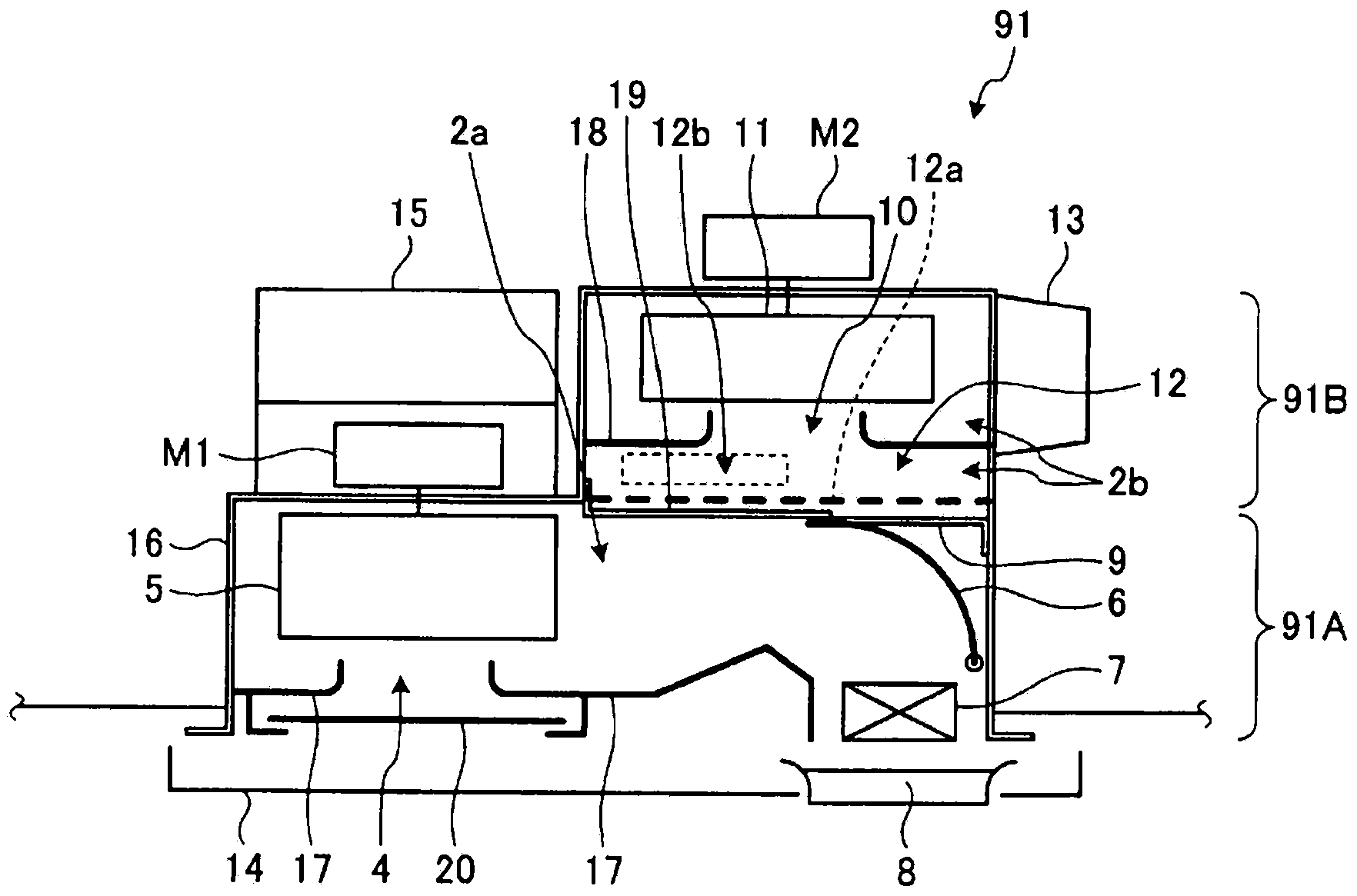
[0041] figure 1 It is a sectional view showing Embodiment 1 of the bathroom dryer of the present invention, figure 2 It is a cross-sectional view showing the downstream side of the circulating air passage when the rotation position of the damper is taken as the ventilation position, image 3 It is a cross-sectional view showing the downstream side of the circulation air path when the rotation position of the damper is set as the dry and cool air position, Figure 4 It is a cross-sectional view showing the downstream side of the circulating air passage when the rotation position of the damper is set to the air drying position, Figure 5 It is a cross-sectional view showing the downstream side of the circulating air passage when the rotation position of the damper is set to the heating position, Figure 6 It is a plan view showing the bathroom dryer of Embodiment 1, Figure 7 It is a cross-sectional view showing the drive unit of the damper in the first embodiment.

[0042] S...

Embodiment approach 2

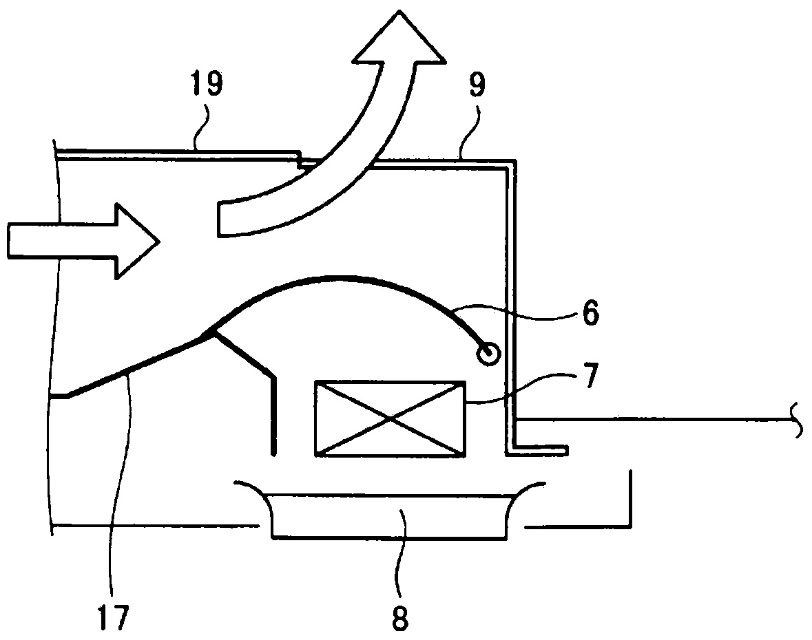
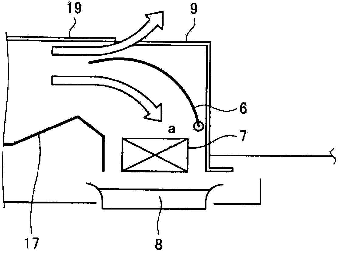
[0079] Figure 8 It is a sectional view showing Embodiment 2 of the bathroom dryer of the present invention, Figure 9 It is a sectional view showing the circulation unit of Embodiment 2, Figure 10 It is a sectional view showing the ventilation unit of Embodiment 2, Figure 11 It is a sectional view showing the bathroom dryer for one room according to the second embodiment.

[0080] Such as Figure 8 As shown, the difference between the bathroom dryer 92 of the second embodiment and the bathroom dryer 91 of the first embodiment is that the circulation unit 92A and the ventilation unit 92B are separate units, and the circulation air passage 2a and the ventilation air passage 2b Formed within respective separate housings 16A, 16B. The circulation unit 92A and the ventilation unit 92B are separable, and the partition plate 19 of the bathroom dryer 91 of Embodiment 1 is abolished, and the top plate of the casing 16A of the circulation unit 92A is extended instead.

[0081] T...


PUM


Abstract

The present invention is provided with: a circulation unit, which is installed on the ceiling of a bathroom and formed by a housing and a bottom plate, and is provided with a downward-facing circulation intake and circulation outlet, and an upward-facing ventilation connection port, and has an internal circulation air duct in which a circulation blower, a damper for opening and closing the ventilation connection port, and a heater are disposed; and a ventilation unit, which is disposed above the circulation unit, is provided with a downward-facing bathroom intake and a horizontal exhaust vent, has an internal ventilation air duct in which a ventilation blower is disposed, and is formed so as to have a width and depth that is less than or equal to the width and depth of the circulation unit.

Description

technical field [0001] The present invention relates to a bathroom dryer for one room that is installed on the ceiling of a bathroom to ventilate, dry, and heat the bathroom, and a multi-room bathroom dryer that can simultaneously ventilate rooms other than the bathroom. Background technique [0002] In the past, bathroom dryers include single-room bathroom dryers that ventilate, dry, and heat the bathroom, and multi-room bathroom dryers that can ventilate rooms other than bathrooms such as dressing rooms and toilets. Many schemes have been proposed about the ventilation air path and the circulating air path. [0003] The multi-room bathroom dryer has two functions: ventilation, drying and heating of the bathroom, and ventilation of other rooms. In the case of independent work of each function, at least 2 air passages are required. For this reason, the multi-chamber bathroom drier is larger in size than the single-chamber bathroom drier with only a bathroom, and the install...

Claims


Application Information

Patent Timeline
Patent Type & Authority Applications(China)
IPC IPC(8): F24F7/06F24D15/00F26B9/02F24F7/00
CPCF24F7/00F24F2007/001F26B9/003F24F2221/34F24F2221/14
Inventor 林俊明宫崎修本木一郎
Owner MITSUBISHI ELECTRIC CORP
Why Eureka
Try Eureka