

Switching structure of button sewing machine and bar tacking machine
The technology of bar tacking machine and buttoning machine is applied in the direction of cloth pressing mechanism, sewing machine components, textile and paper making, etc., which can solve the problems of long switching time, delayed construction period, and increased cost, and saves the use cost and labor cost. , the effect of reducing the switching time and reducing the impact
- Summary
- Abstract
- Description
- Claims
- Application Information
AI Technical Summary
Problems solved by technology
Method used
Image

Examples
Embodiment Construction
[0026] The present invention will be further described below with specific embodiment, see figure 1 -9:
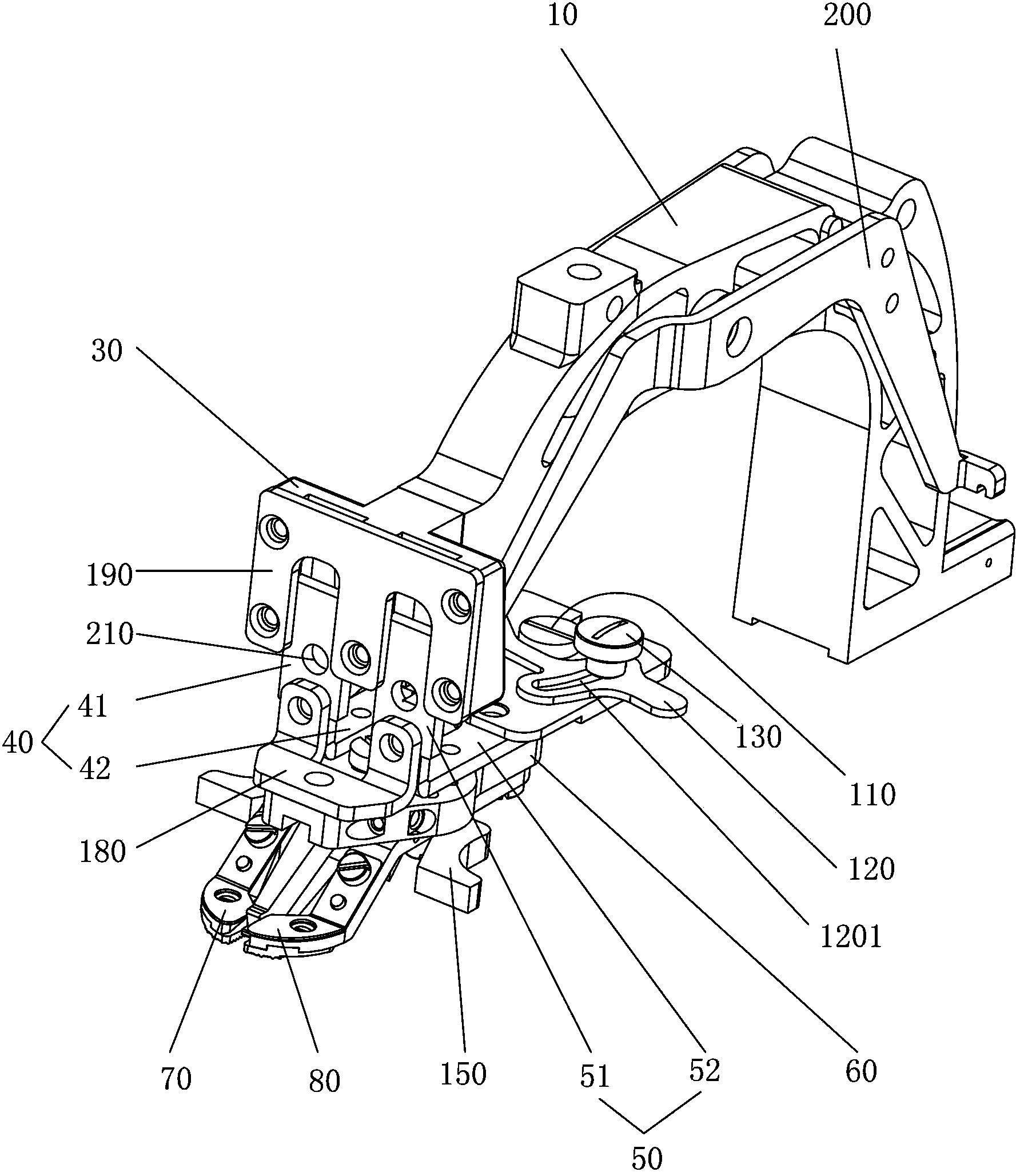
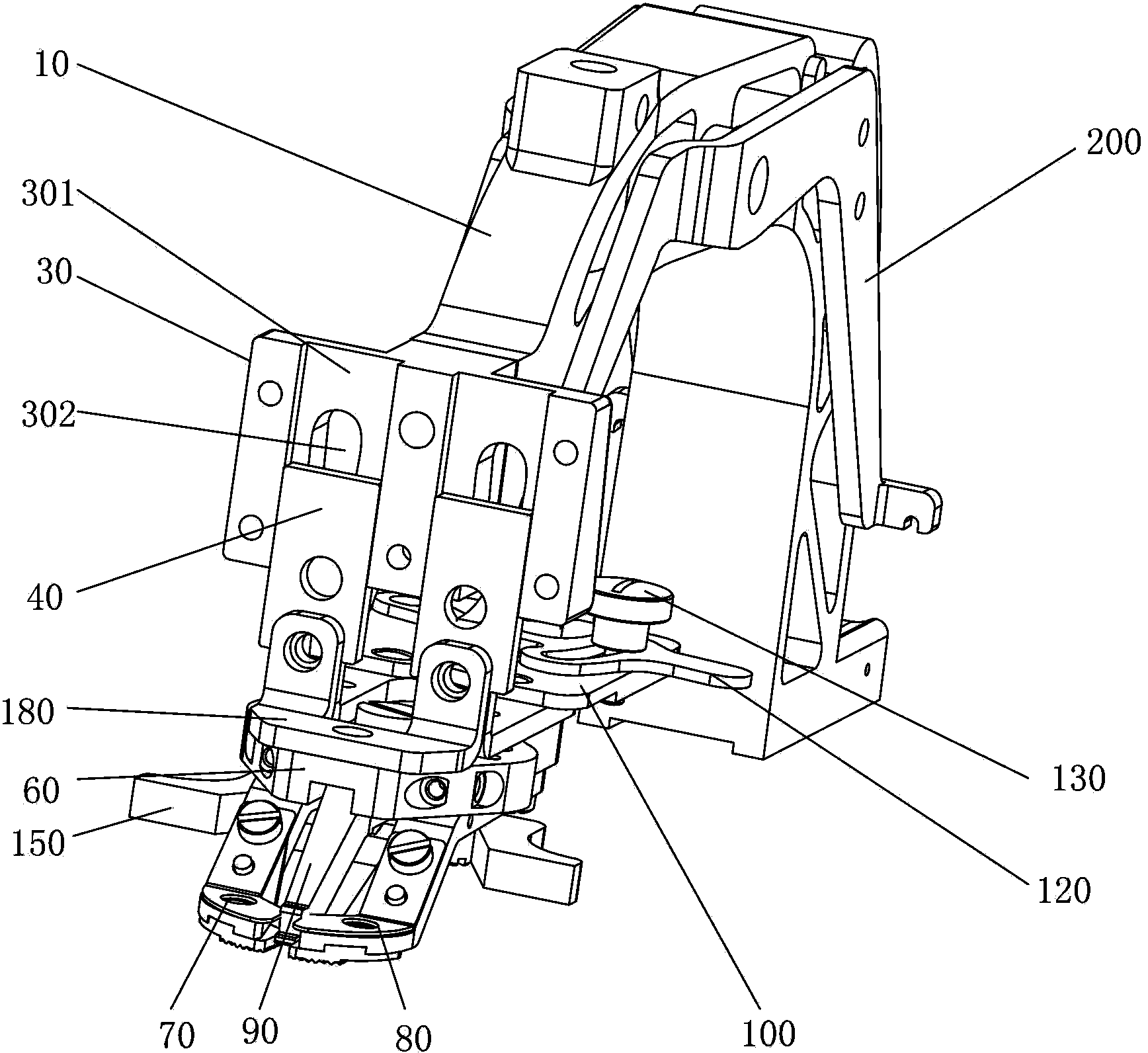
[0027] A switch structure between a button tacking machine and a tacking machine, in which a tacking adapter 20 or a tacking adapter 30 is provided at the front end of a supply rack 10, and a tacking presser foot device or nailing device is connected to the tacking adapter 20 accordingly. The button adapter 30 is connected with a button presser foot device.
[0028] The front side of the above-mentioned button adapter 30 is provided with two parallel presser foot installation grooves 301 at intervals, and the presser foot installation grooves 301 are respectively provided with strip-shaped opening grooves 302 parallel to the presser foot installation grooves 301. A pin hole and a threaded hole or two threaded holes are provided on the button adapter 30 between the foot mounting grooves 301, and a pin hole and a threaded through hole or two threaded holes are corresponding...
PUM
 Abstract
Description
Claims
Application Information