Detergent dosage controller

A detergent injection and controller technology, which is applied in the direction of washing machine control devices, washing devices, tableware washing machines/rinsing machines, etc., can solve problems such as inaccurate injection accuracy, complex structure, and blocked equipment operation, and achieve compact structure , Simple structure and simple assembly

Active Publication Date: 2013-11-20
HANGZHOU KAMBAYASHI ELECTRONICS
View PDF9 Cites 33 Cited by
  • Summary
  • Abstract
  • Description
  • Claims
  • Application Information

AI Technical Summary

Problems solved by technology

[0010] The present invention aims to solve the problems that the structure of the liquid detergent dispensing device configured in the current washing equipment is relatively complicated, the dispensing accuracy is not accurate enough, and the operation of the equipment is hindered due to the easy residual solidification of detergent, etc., and a detergent dispensing controller of the present invention is provided for this purpose. The detergent dosing controller is simple in structure, small in size, easy to install and use, the detergent in the equipment is not easy to remain, and the dosing accuracy is high

Method used


Image

  • Detergent dosage controller
  • Detergent dosage controller
  • Detergent dosage controller

Examples


Embodiment 1

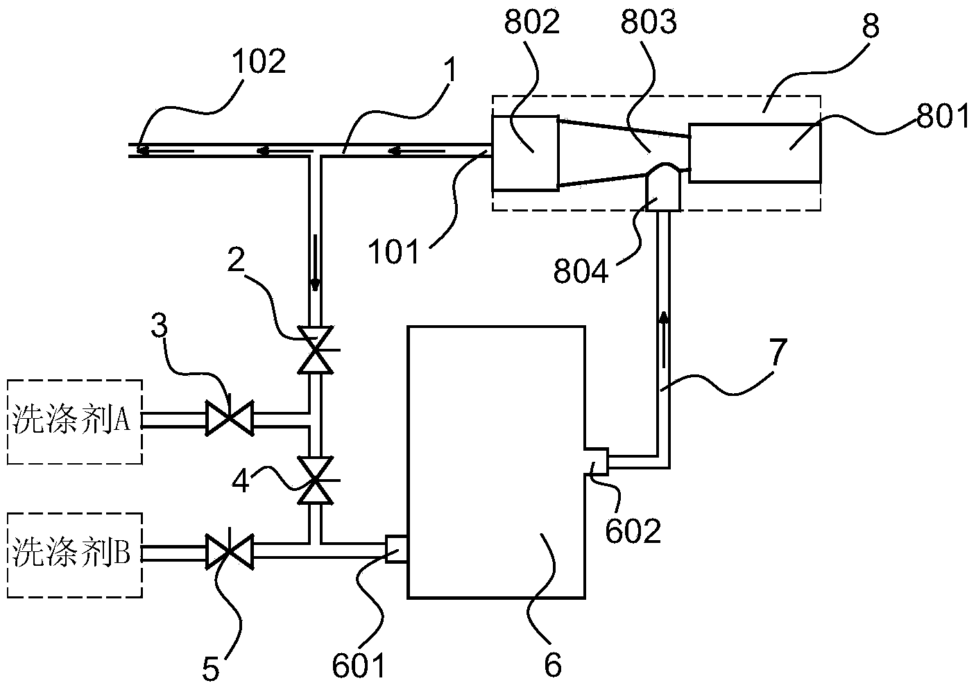
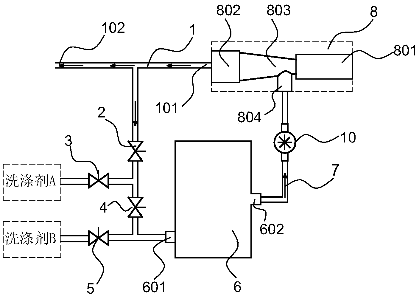
[0044] The detergent dispensing controller has a main channel 1, one end of the main channel is the inlet 101 of the input liquid flow, and the other end of the main channel is an outlet 102 that can be connected to the water inlet of the washing bucket, and is provided with valve A2, valve B3, valve C4, valve D5, liquid collecting chamber 6 and Venturi negative pressure generator 8, the inlet of valve A is connected with the main channel bypass, the inlet of valve B can communicate with the liquid storage tank of detergent A, the valve A and valve B The outlet is connected to the inlet of valve C, the inlet of valve D can be connected to the liquid storage tank of detergent B, the outlets of valves C and D are connected to the inlet 601 of the liquid collection chamber, and the outlet 602 of the liquid collection chamber passes through the return channel 7 is in communication with the negative pressure port 804 of the Venturi negative pressure generator, the outlet 802 of the ...

Embodiment 2

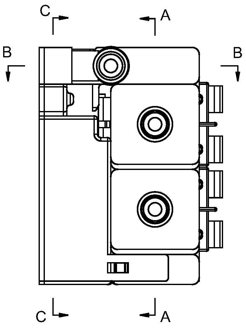
[0046] In this example, the detergent injection controller, see image 3 , 4 , 5, 6, with an integrated valve, the integrated valve is provided with a main channel 1, valve A2, valve B3, valve C4, valve D5, liquid collection chamber 6, return channel 7 and Venturi negative pressure generator 8, the main channel One end is the inlet 101 of the input liquid flow, and the other end of the main channel is the outlet that can be connected to the water inlet of the washing tub through a connecting pipe. The inlet 201 of the valve A is connected to the main channel through the bypass port 103 of the main channel 1, and the inlet of the valve B3 It can communicate with the liquid storage tank of detergent A. The outlets of valve A and valve B are connected to the inner cavity 17 and communicate with the inlet of valve C4. The inlet of valve D5 can be connected with the liquid storage tank of detergent B. Valve C The outlet of the valve D is connected to the inner chamber 2 18, the in...

Embodiment 3

[0053] In this example, the detergent injection controller, see Figure 7 , Figure 8 , is to add valve E20, valve F21 and solenoid valve assembly three including piston cap three 22, piston three 23, electromagnetic coil three 24 on the basis of example two; the outlets of valve C and valve D in this example are connected to inner chamber two 18 and It is connected with the inlet of valve E20, the inlet of valve F can be connected with the liquid storage tank of detergent C, the outlets of valve E and valve F are connected to the inner chamber 3 19, and the inner chamber 3 is connected with the inlet 601 of the liquid collecting chamber 6; The first cavity, the second cavity and the third cavity are connected together;

[0054] The valve E20 and the valve F21 correspond to the solenoid valve assembly 3, the outlet of the valve E and the outlet of the valve F are connected with the inner chamber 19 of the integrated valve, and the coaxial lines in the inner chamber 3 are oppo...


PUM


Abstract

The invention provides a detergent dosage controller which is simple in structure and convenient to use and can prevent detergent from being solidified to hinder the use. The detergent dosage controller comprises a main channel; an inlet for inputting a liquid stream is formed in one end of the main channel; an outlet which can be connected with the water inlet of a washing barrel is formed in the other end of the main channel; the detergent dosage controller is provided with a valve A, a valve B, a valve C, a valve D, a liquid collecting cavity and a Venturi negative pressure generator; the inlet of the valve A is connected with a branch of the main channel; the inlet of the valve B can be communicated with a liquid storage tank for detergent A; the outlets of the valve A and the valve B are communicated with the inlet of the valve C; the inlet of the valve D can be communicated with a liquid storage tank for detergent B; the outlets of the valve C and the valve D are communicated with the inlet of the liquid collecting cavity; the outlet of the liquid collecting cavity is communicated with the negative pressure port of the Venturi negative pressure generator through a backflow passage; the outlet of the Venturi negative pressure generator is communicated with the inlet of the main channel; the inlet of the Venturi negative pressure generator is connected with a water source. The detergent dosage controller is applicable to electric clothes washing machines or dish washing machine.

Description

technical field [0001] The invention relates to a device for dispensing liquid preparations, in particular to a liquid washing dispensing control device equipped on electric washing machines such as electric washing machines and electric dishwashers. Background technique [0002] In the past, the liquid detergent (or softener, softener, sterilizing solution, etc.) of electric washing equipment such as electric washing machines and electric dishwashers using liquid detergent was added by the user to store the liquid detergent to be injected in advance. Inside the container, the washing equipment flushes the washing detergent into the washing bucket through water flushing or other mechanical methods according to the washing process. In this method, the dosage of detergent depends on the arbitrariness of the user's operation, and detergent needs to be added to the container during each washing process. With the continuous improvement of detergent liquefaction, it is an applica...

Claims


Application Information

Patent Timeline
Patent Type & Authority Applications(China)
IPC IPC(8): D06F39/02A47L15/44
CPCA47L15/4427D06F39/022Y10T137/2599Y10T137/87265Y10T137/87338Y10T137/87354D06F33/37A47L15/4217A47L15/44A47L2501/01A47L2501/07
Inventor 王华鲍鹏飞
Owner HANGZHOU KAMBAYASHI ELECTRONICS
Why Eureka
Try Eureka